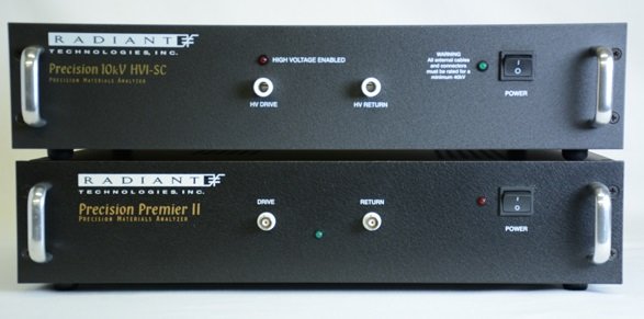
Click to Jump to Tester Specifics Tester Accessories Support Documentation Specifications Vision Software Precision Premier II Ferroelectric Tester The Precision Premier II is an advanced tester that has a large test envelope in terms of frequency response, voltage range and accuracy. The Premier II has a fast hysteresis frequency rating of 250KHz at +/-10V built-in…
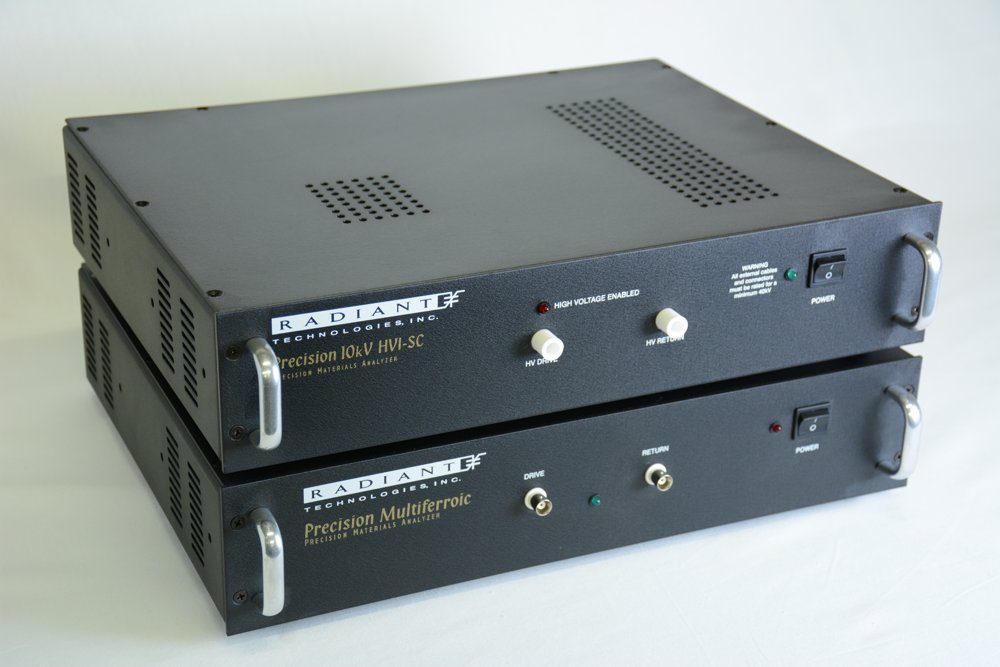
The Most Advanced Test System on the Market Meet the Precision Multiferroic II Ferroelectric Tester. It has a unique frequency rating of 270KHz at +/-100V built-in to the system. The Multiferroic II tester makes testing of thin films and bulk ceramics a fast and simple process. It captures 32,000 points at 2 MHz to achieve exquisite frequency resolution in DLTS or PAINT measurements. The Precision Multiferroic II is offered with a variety of internal amplifiers. The Multiferroic II is offered with a ±100V, 200V and 500V built-in drive volt option. It can be expanded to 10kV with the addition of a high voltage interface and an amplifier. The Precision Multiferroic II executes hysteresis, pulse, leakage, IV, and CV (and many other tasks) measurements without changing sample connections. With the addition of extra fixtures, the Precision Multiferroic II can measure pyroelectric properties, magneto-electric properties, transistor characteristics, cryogenic properties, bulk ceramic and/or thin film piezoelectric properties. Specifications Tester Parameter - Multiferroic II - Voltage Range (built-in drive voltage): ±10V, ±30V, ±100V, ±200V or ±500V built-in - Voltage Range with an external amplifier and high voltage interface (HVI): 10KV - Number of ADC Bits: 18 - Minimum Area Resolution: 0.80fC - Minimum Area Resolution (assuming 1 ADC bit = 1μC/cm2): 0.080μ2 - Maximum Charge Resolution: 5.26mC - Maximum Area Resolution (assuming saturation polarization = 100μC/cm2): 52.6cm2 - Maximum Charge Resolution with High Voltage Interface (HVI): 526mC - Maximum Area Resolution (assuming saturation polarization = 100μC/cm2) w/o HVI: 100cm2 - Maximum Hysteresis Frequency: 270KHz @ +/-100V 100KHz @ +/-200V 5KHz @ +/-500V - Minimum Hysteresis Frequency: 0.03Hz - Minimum Pulse Width: 0.5μs - Minimum Pulse Rise Time (5V): 400ns - Maximum Pulse Width: 1s - Maximum Delay between Pulses: 40ks - Internal Clock: 25ns - Minimum Leakage Current (assuming max current integration period = 1 seconds): 1pA - Maximum Small Signal Cap Frequency: 1MHz - Minimum Small Signal Cap Frequency: 1Hz - Output Rise Time Control: 105 scaling - Input Capacitance: -6fF - Electrometer Input All Test Frequencies for all test at any speed: Yes The minimum area resolution under actual test conditions depends upon the internal noise environment of the tester, the external noise environment, and the test jig parasitic capacitance. Tester specifications are subject to change without notice. Vision Data Acquisition & Management System Software Included Vision dramatically increases the productivity of the researcher, reducing the time required to acquire data in an experiment. Vision’s enhanced productivity directly reduces cost of test. Vision dramatically increases the complexity of the research that may be accomplished by allowing researchers to combine different measurement tasks with environmental controls into an automated test procedure managed by programmable logic embedded with automated data collection, analysis and plotting tools. Materials Testers running under the Vision Materials RDP Operating System reduces Cost of Test by a factor greater than 10 over any other ferroelectric tester. - A Library of 155 measurement, analysis, plotting, program control, and documentation tasks. - An Editor to arrange multiple tasks together from the Library into a Test Definition. - An Execution Engine to read and execute the Test Definition. - An amorphous database engine to Archive everything that happens in each Test Definition. Radiant’s Precision Line of Test Systems are driven by Vision Software. Vision is a revolutionary software package that provides exceptional freedom to design, conduct, and review all procedures associated with any material experiment. The Vision test environment will collect all data acquired in a test sequence and organize it in archived data structures along with the test sequence definitions and data analysis tools. The experiment can always be recalled or reproduced. Data and test conditions can be shared over the Internet to allow collaborative research. Measurements include, but are not limited to - Hysteresis, Leakage, Charge, Retain, Resist, I/V, Fatigue, C(V), PUND, Imprint, Leakage Current, Remnant Hysteresis, Small signal CV, imprint, retention, and piezoelectric displacement from one hardware configuration. Radiant offers optional Piezoelectric, Magnetoelectric, Transistor, and Pyroelectric software programs
CATEGORY

Your Analysis Assistant Vision is a revolutionary software package that provides exceptional freedom to design, conduct, and review all procedures associated with any material experiment. The Vision test environment will collect all data acquired in a test sequence and organize it in archived data structures along with the test sequence definitions and data analysis tools. The experiment can always be recalled or reproduced. Data and test conditions can be shared over the Internet to allow collaborative research. Try Vision Software for Free Vision has Four Interconnected Units Measurement tasks pass data to the plotting and analysis tasks in the Test Definition during execution. Program control tasks manage external instruments, control the order of task execution, and adjust test parameters during execution of a Test Definition. Radiant’s Non-linear Materials Testers running under the Vision Materials RDP Operating System reduces Cost of Test by a factor greater than 10 over any other ferroelectric tester. - 1 A Library of 155 measurement, analysis, plotting, program control, and documentation tasks. – An Editor to arrange multiple tasks together from the Library into a Test Definition. – An Execution Engine to read and execute the Test Definition – An amorphous database engine to Archive everything that happens in each Test Definition. - 2 An Editor to arrange multiple tasks together from the Library into a Test Definition. - 3 An Execution Engine to read and execute the Test Definition. - 4 An amorphous database engine to Archive everything that happens in each Test Definition. The Power of Vision Test Definitions and Data Sets Radiant’s Precision Line of Test Systems are driven by Vision Software. Vision Software is a framework that loads a variable series of independent agents known as Tasks. Tasks are configurable objects that perform the procedures of an experiment and collect and analyze any measured data. Such an experiment is called a Test Definition. The true power of Vision is in grouping Tasks together into Test Definitions to form custom experiments. The user is not tied to running one specific Task at a time. The Test Definitions may consist of any number of Measurement Tasks. Researchers can create a DataSet to hold any number of arbitrary Test Definitions. A single Test Definition - the Current Test Definition (CTD) - represents an experiment that is ready for immediate execution. On execution, the Test Definition, along with the measured data, are permanently archived to the DataSet as and Executed Test Definitions (ETD). Vision's "Innovative Test Editor" let's researchers create and document complex Test Definitions using type-specific icons to represent Tasks. All Tasks include a Task Instructions button on their configuration (and data presentation) dialogs. The Task Instruction pages include Task theory, where appropriate, a complete and detailed discussion of every control on the configuration dialog, a detailed discussion of the Task execution and a history of changes to the Task. New Tasks Additional data filters and measurement tasks have beenadded to the VISION library, including: - 1 The plotting of Sensor2 measurements - 2 Noise reduction tasks. - 3 Settinga magnetic field over GPIB. - 4 Triggering external instruments from the SYNC signal. - 5 Independent sensor read Tasks. - 6 Capture of capacitor response to real-time environmental stimuli. - 7 Measurement of capacitor transients after a pulse. - 8 Movies- Vision now has the capacity to export JPEG images of its plots real timeduring Test Definition Execution. These JPEG images are titled and ordered ina manner that allows quick import into movie maker programs. Data Mining Invoking the data mining wizard allows the user to sort through all of the DataSets on the computer to pull out and plot together any tests. With DM, it is now possible to create plots showing the entire lifetime of a particular sample even if that lifetime involves years of tests. It is also possible to compare the sample response to small changes in the same test run on that sample. Tasks Hardware Tasks These are Tasks that send signals to a tester through the driver and apply a voltage profile to the sample. These also may communicate with other instruments attached to the tester or to the host computer. Hardware Tasks normally apply a voltage profile to the sample. Testers may apply voltages of up to ±10 Volts, ±100 Volts, ±200 Volts, or ±500.0 Volts depending on tester model. Voltages of up to ±10,000 Volts may be applied with the addition of an accessory High-Voltage Interface (HVI) and High Voltage Amplifier (HVA). Hardware Tasks include: Waveform Applies a sine, square, triangle or user-defined voltage waveform to stress the sample. The waveform is of user-defined voltage, frequency and duration. DC Bias Applies a constant user-defined voltage to the sample for a user-defined duration. Measurement Tasks These are Hardware Tasks that receive data from the tester. Measurement Tasks include, but are not limited to: Hysteresis This Task measures sample polarization (μC/cm 2) response to a Task-applied voltage profile. The profile is of user-specified maximum voltage and period (ms) (Period = 1000/frequency (Hz)). Profiles are normally standard bipolar (triangular), but may be monopolar, double-bipolar, sinusoidal or user-specified. Small Signal Capacitance This measurement captures the sample's capacitance as a function of voltage. It measures the capacitance at each voltage step using a very small stimulus signal to eliminate polarization -switching components of the sample response. PUND A standard five-pulse ferroelectric sample characterization measurement that captures both switching (remanent + non-remanent) and non-switching (non-remanent) polarization (μC/cm2). Pulse width and voltage are under user control. Fatigue Performs a series of stress/measure sequences. In the stress sequence the sample is submitted to a switching waveform. At the end of the waveform period, a PUND measurement is made to capture the sample’s polarization response. Each subsequent stress period may have its duration increased to better serve a logarithmic analysis. Leakage Captures the current through a sample induced by a steady-state, DC Bias voltage. Voltage and measurement duration are user-defined. Curve Energy Determines the energy returned and the energy lost from a charged capacitor. It is useful for measuring power capacitors for new energy generating systems. General Monopolar The General Monopolar Task allows up to five independently configured monopolar Hysteresis measurements to be made in sequence in order to execute a PUND measurement using continuous waveforms. Each measurement may be preceded by an unmeasured presetting pulse or poling DC Bias period. Optional Tasks Include: Piezo-Electric Captures a sample’s displacement as a function of voltage profile along with the sample’s polarization response. An external displacement measurement instrument must be attached to the tester to make this measurement. Magnetoelectric Radiant’s new Magnetoelectric Response Task allows the user to measure the magnetoelectric coupling coefficient in multiferroic materials and composite magnetopiezoelectric devices. The test stimulates a sample with a small AC magnetic field while measuring its charge generation. Pyro-Electric Sets the sample to a series of temperature by performing GPIB control of an external thermal device. At each temperature it captures the sample’s polarization response and/or small-signal capacitance. These are combined to calculate the pyroelectric coefficient. Transistor Radiant has introduced an I²C digital-to-analog converter product that can be attached to the Precision Premier II or Multiferroic Test System and is controlled from Vision. The addition of this extra voltage source makes it possible for the testers to measure the performance of thin-ferroelectric-film gate transistors (TFFTs and MFSFETs). DLTS Deep Level Trap Spectroscopy Task allows the user to measure the population of traps filled during a voltage pulse of a non-linear material and measure the decay rate of the trapped population as a function of temperature. PAINT PAINT was originally designed to capture the mechanical and acoustic vibrations induced in an ink jet chamber by the pulsing of the piezoelectric element to re an ink droplet. In reality, the PAINT Task in Vision can be used to capture the acoustic response of any activity, including SONAR type measurements in a water tank. Filters These are Tasks that collect, operate on, store and plot data from one or more Measurement Tasks or other Filters. Filter categories include: Collect/Plot Simple data collection and plotting. Mathematical Analysis Combine two measured data vectors into one through addition, subtraction, multiplication or division or perform single vector manipulation on one or more input data vectors. Single vector operations include linear scaling and offset, integration and differentiation. Averaging Average multiple data vectors together to form a single vector, average one or more single vectors with itself over multiple iterations in a Branch Loop or perform statistical analysis on one or more single vectors. Statistical analysis includes maximum, minimum, mean and standard deviation. External Sensor Tasks These are Tasks that import or measure tester SENSOR (1 and/or 2) Port Voltages. SENSOR Collect/Plot Filter Extract SENSOR 1 port voltages from Input Measurement Task Data if SENSOR 1 capture is enabled. SENSOR 2 Collect/Plot Filter Extract SENSOR 2 port voltages from Input Measurement Task data if SENSOR 2 capture is enabled. Read SENSOR Task These Tasks allow the user to directly take a reading of the voltage on SENSOR or SENSOR 2 without having to execute a subsidiary task like Hysteresis. SENSOR Oscilloscope The oscilloscope task presents a real time display of the voltage on one of the sensor ports of the LCII, Premier, or Multiferroic testers. External Instrument Control These are Tasks that communicate with remote instruments through a GBIP bus. LCR Meter This task allows the user to query an external LCR meter for its measurements including capacitance, loss, and Tan Delta. Set Field This task allows the user to specify a setting for the superconducting magnet connected to a Quantum Design 6000 controller. Temperature This Task sets the sample to a series of temperature by performing GPIB control of an external thermal device. At each temperature it captures the sample’s polarization response and/or small-signal capacitance. These are combined to calculate the pyroelectric coefficient. Program Control Program Control Tasks are Tasks that control Test Definition sequencing and provide for general Documentation. Branch Tasks These are Tasks that allow the program to sequence repeatedly over a sequential subset of the Tasks in a Test Definition. Sequencing continues until some condition, that is changing over the Branch iterations, reaches a user-specified threshold. Exit Tasks These are Tasks that terminate Test Definition execution prematurely based either on comparing an experimental value to a threshold or direct user interaction. If/Then and Endif This Task pair allows a sequential subset of the Tasks in a Test Definition to be omitted from execution based on the comparison of an experimental value to a threshold. Start Time and Elapsed Time The Start Time Task establishes a baseline date/time stamp when executed. The Elapsed Time records the elapsed of Task execution relative to the start time date/time stamp. Documentation Documentation Tasks include the General Information Task that allows extensive text description of the purpose and configuration of the Test Definition, composition of the sample or any other pertinent information. The Hyperlink Task allows links to external files and URLs to be recorded at run-time. Label Tasks allow brief documentation to be recorded by the user at run-time
CATEGORY
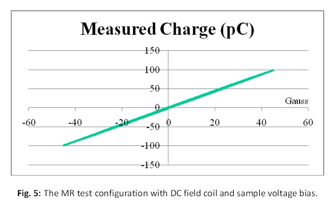
Radiant's Magnetoelectric Bundle offers researchers a complete platform to efficiently characterize magnetic coupling of Multiferroic or Magneto-piezoelectric devices. Radiant's Magneto-electric Bundle is offered in a Bulk Ceramic and Thin Film Testing Package. The accessory adds four items to the Radiant tester: 1. ME Shield Box: The sample holder that shields the sample electrically while also mounting magnetic field sensors directly at the sample location. This is the only way to be sure of the magnetic field at the sample during a test. Also, most modern ME samples generated only a few picocoulombs of charge which cannot be seen in a laboratory without electrical shielding due to 50Hz or 60Hz noise. 2. Lakeshore MH-6 Helmholtz coil for applying small magnetic fields up to 50 Oersted. - You do not have to purchase this item if you already have your own magnetic coils or prefer those of another manufacturer. 3. Radiant 2.5 Ampere Current Source for driving the magnetic coil. - Again, you do not need this item should you already have a voltage controlled current amplifier. 4. A Lakeshore Hall Effect magnetic field sensor - used for calibrating the test fixture, especially if you provide your own coils and current amplifiers. Radiant does not supply DC magnetic field coils but the MER Task in Vision will control external DC coils to set a DC magnetic field across the sample. The Magneto-electric Hardware/Software Bundle Includes: - Radiant Precision Current Source CS-2.5 (includes 2 voltage outputs) - current sensor - 2.5-amp current source - Helmholtz Coil Test Fixture for Bulk Ceramics or Thin Films - Magneto-electric Software Task The Magnetoelectric Response (MER) Task in Vision executes a single or double sinusoidal or triangular magnetic field waveform across the sample inside the Shield Box inside the Helmholtz coil while measuring the charge generated by the sample in response to the changing magnetic field. It is the exact parallel to the classic polarization hysteresis loop measurement except for the replacement of the voltage waveform with a magnetic field waveform. The DRIVE output of the tester is connected to the voltage input of a current source which drives the magnetic coil. In addition to the AC magnetic coil, Vision will set DC magnetic fields in a separate, much larger coil that can be placed across the sample. There are a wide variety of measurements besides the magnetoelectric response that can be executed with the Magnetoelectric Bundle. - 1 Polarization Hysteresis vs Magnetic Field - 2 Remanent Polarization vs Magnetic Field - 3 PUND vs Magnetic Field - 4 Conduction vs Magnetic Field (the so-called magneto-resistive memory effect) - 5 IV vs Magnetic Field - 6 Small Signal Capacitance vs Magnetic Field - 7 Voltage-to-Magnetic Field Task - Sets a voltage on the input of an external current amplifier to set a DC magnetic field. - 8 A Calibration Task - 9 The MER Task - measures magnetoelectric response of a capacitor - 10 The Single Point C/V MR Task - measures the sample small signal capacitance after setting a specified DC magnetic field value. Radiant's Magneto-electric Bundle hooks up to existing coils on the market such as GMW and other manufacturers.
CATEGORY
The Precision Premier II is an advanced tester that has a large test envelope in terms of frequency response, voltage range and accuracy. The Premier II has a fast hysteresis frequency rating of 250KHz at +/-10V built-in to the system. The Premier II execute tests to 100 kHz below 10 Volts, making it useful for both bulk and thin film capacitors. The Premier II is capable of measuring thin ferroelectric film capacitors down to 0.1 square microns. Using up to 32,000 points with 18-bit resolution. The Precision Premier II is offered with a variety of internal amplifiers. The Precision Premier II is offered in a ±10V, 30V, 100V, 200V, and 500V built-in drive volt option. The Precision Premier II can be expanded to 10kV with the addition of a high voltage interface and amplifier. The Premier II tester makes testing of thin films and bulk ceramics a fast and simple process. The Precision Premier II executes hysteresis, pulse, leakage, IV, and CV (and many other tasks) measurements without changing sample connections. With the addition of extra fixtures, the Precision Premier II can measure pyroelectric properties, magneto-electric properties, transistor characteristics, cryogenic properties, bulk ceramic and/or thin film piezoelectric properties. Specifications: - Voltage Range (built-in drive voltage): ±10V, ±30V, ±100V, ±200V or ±500V built-in - Voltage Range with an external amplifier and high voltage interface (HVI): 10KV - Number of ADC Bits: 18 - Minimum Charge Resolution: 0.80fC - Minimum Area Resolution (assuming 1 ADC bit = 1μC/cm 2): 0.080μ 2 - Maximum Charge Resolution: 5.26mC - Maximum Area Resolution (assuming saturation polarization = 100μC/cm 2): 52.6cm 2 - Maximum Charge Resolution with High Voltage Interface (HVI): 526mC - Maximum Area Resolution (assuming saturation polarization = 100μC/cm2) w/o HVI: 100cm 2 - Maximum Hysteresis Frequency: 250KHz @ 10V 50KHz @ 30V 50KHz @ 100V 50KHz @ 200V 2KHz @ 500V - Minimum Hysteresis Frequency: 0.03Hz - Minimum Pulse Width: 0.5μs - Minimum Pulse Rise Time (5V): 400ns - Maximum Pulse Width: 1s - Maximum Delay between Pulses: 40ks - Internal Clock: 25ns - Minimum Leakage Current (assuming max current integration period = 1 seconds): 1pA - Maximum Small Signal Cap Frequency: 1MHz - Minimum Small Signal Cap Frequency: 1Hz - Output Rise Time Control: 10 5 scaling - Input Capacitance: -6fF - Electrometer Input All Test Frequencies for all test at any speed: Yes The minimum area resolution under actual test conditions depends upon the internal noise environment of the tester, the external noise environment, and the test jig parasitic capacitance. Tester specifications are subject to change without notice.
CATEGORY
