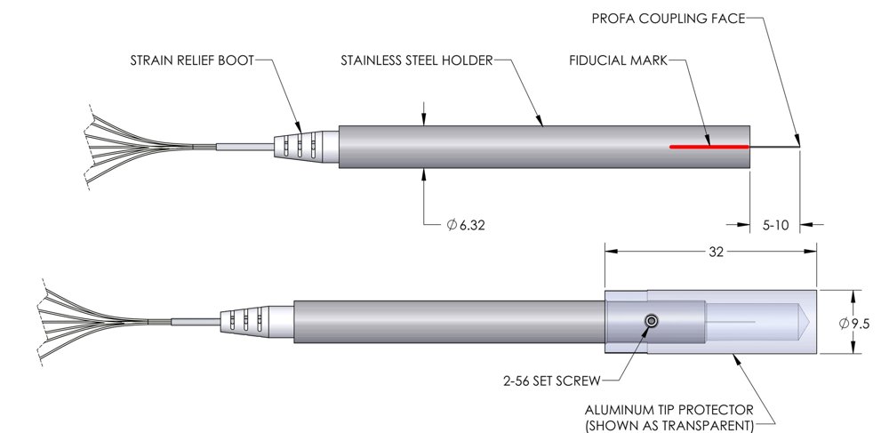
Pitch Reducing Optical Fiber Array Pitch Reducing Optical Fiber Arrays, or PROFAs, are compact, precisely positioned arrays of, typically singlemode, fibers. PROFAs have standard fiber pigtails but their monolithic glass endface provides a high-density array with typical channel spacing of 37 to 50 µm, positioned with submicron accuracy, that retain the mode field size of the pigtail fiber. PROFA -61-Channel Array. Micrograph of coupling endface is shown to the right, displaying all 61 channels in the hexagonal array The above description describes our standard products which have primarily been optimized for 1550 nm. However, Chiral Photonics, Inc. (CPI) has worked on many custom products. PROFAs are a powerful tool that offer broadband operation, have been optimized for other wavelengths, mode field sizes, lattice configurations, channel counts and other application needs. More specifically but not exhaustively: Wavelength 1550 and 725 nm are wavelengths where subcomponents have been optimized. Devices have been fabricated for applications from 400 to 2000 nm. Also, devices are relatively broadband. Non-optimized subcomponents can be used at other wavelengths with an often acceptable insertion loss penalty. Of course, development of optimized subcomponents is always an option we are happy to discuss. Spot Size Conversion PROFAs can be designed to maintain, reduce or enlarge the mode field diameter (MFD) at the PROFA endface as compared to the MFD in the fiber pigtails. At 1550 nm, typical output MFDs are 10 or 6 µm. However, other needs have been accommodated. For example, high fill-factor devices (mode field diameters approaching channel spacing) have been provided for free-space communications applications. Please note that the choice of endface MFD must consider the crosstalk needs of the application. MFDs approaching the channel spacing will result in higher crosstalk. Single channel PROFAs have also been provided to serve as spot size converters. Please speak to us about your specific needs. Channel Spacing and Alternate Lattice Shapes Optimal channel spacing for the triangular or hexagonal pattern shown is typically 37 µm. However, a spacing of 35-50 µm can be accommodated. Smaller channel spacing can also be accommodated, but crosstalk requirements must be considered. Submicron channel positioning precision is somewhat a function of the tapering draw ratio, so larger channel spacing may compromise positioning error from the ‘perfect’ grid somewhat. Alternate lattice shapes, such as square, circular, and linear placements of the channels, have been provided. Please speak to us about your specific needs. Fiber Pigtail Jacketing and Connectors PROFAs can be provided with jacketing over the bare fiber, to add protection, and connectors on the fiber pigtails, to provide pluggability. Chiral has provided assemblies incorporating other components, armored and ruggedized cabling and connectors ranging from FC/UPC, LC/APC to MTP and specialty mil-spec connectors. Speak to us about your specific needs. PROFA packaging and holding There is typically a metal package that encloses the base (untapered portion) of the PROFA for protection and handling of the PROFA and its pigtails. This minimal ( M ) metal package can be gently clamped to position the PROFA. Holding the PROFA’s glass portions is strongly discouraged. This package’s diameter can also be expanded, referred to as a holder-compatible ( HC ) package, to enable simpler mounting of the PROFA in standard mounts. The holder-compatible package can be extended to protect more of the tapered endface. Leaving the endface extended beyond the package is recommended to enable endface cleaning, similar to a fiber endface. However, a cover is added to holder-compatible packages to protect the endface when in transit or not in use. The holder-compatible package is designed to simplify holding in standard 6.35 mm (0.25″) diameter fiber chuck holders. See technical notes below. Polarization Polarization maintaining PROFAs have been provided with PM pigtails for a variety of wavelengths. Polarization extinction ratios are limited to 10-15 dB for relatively small channel counts, less than 12 channels. Larger channel count PM PROFAs are possible but may require non-recurring engineering fees, depending on the application needs and the number of channels required. PM PROFAs will also need specification of the orientation of the slow axis at the endface and of the fiber pigtail connector keys, if applicable. See technical notes below. Custom PROFAs with circularly polarizing channels, incorporating circular polarizer technology [link to circular polarizer], have also been fabricated to provide less alignment-sensitive output. Endface Polish The endface polish can be flat or angled to reduce back-reflections. In addition to specifying the endface angle, it may be necessary to specify the polish angle relative to the channels. See technical notes below. Testing Testing and the data provided for each PROFA will somewhat depend on the application and PROFA specifics. Please discuss with us what testing is needed for your application needs. Some parameter values for a typical 1550 nm PROFA are as follows. Please speak to us about your needs. Custom PROFAs have been supplied to address many specific application needs: Parameter Unit PROFA Central wavelength (λc) 1 nm 1550 Mode field diameter 2 µm 6 or 10 Bandwidth nm > 50 Insertion loss 3 dB < 1 Optical return loss 4 dB < -40 Crosstalk dB < -35 Number of channels 5 1-91 Channel spacing 6 µm 35-50 Typical average channel deviation 7 µm ≤ 0.1 x λc Operating temperature C -40 to +85 Storage temperature C -70 to +85 Pigtails 8 1 m long, coated SM fibers Package type 9 M or HC - Other wavelengths available upon request. - Measured, typically in the near-field, as 1/e 2 Other mode field sizes available upon request. - Measured from fiber pigtail to device tip, per channel. - Intrinsic to device. - Typical array is hexagonal. Other lattice arrays have been accommodated. Larger channel counts can also be accommodated. A single channel is obviously not an array but single channel PROFAs have been used to provide spot size conversion. - Other channel spacing sizes can also be accommodated. - Measured displacement of PROFA channel from its “perfect array” channel position. Will be dependent on array size and pitch. As indicated, and similar to fiber, the target is typically to have the position within 10% of the mode field diameter. So, for example, if the MFD = 10 µm, the position of each channel is targeted to be within 1 µm of the perfect position. - Other pigtails, connectorization and other pigtail lengths are available upon request. - Please speak to us about your custom package, splicing and assembly needs. Ordering Information When purchasing a PROFA, please use the guide below to determine the best configuration for your application. Please do not hesitate to contact us with any questions. Exemplary configurations Below are examples of different configurations. Configuration 1 PROFA-H-07/35-SM-01-1550-LC/APC-00-00-MN-C: - PROFA, hexagonal array, 7 channels, 35 µm spacing - SMF28 fiber pigtails, 1 meter long - 1550 nm central wavelength - LC/APC connectors, unjacketed, flat endface polish - Minimal package Configuration 2 PROFA-S-04/50-SM-02-1550-FC/UPC-FT-00-HC-C: - PROFA, square array, 4 channels, 50 µm spacing - SMF28 fiber pigtails, 2 meters long - 1550 nm central wavelength - FC/UPC connectors, jacketed, flat endface polish - Holder-compatible package Configuration 3 PROFA-S-04/50-SM-02-1550-FC/UPC-FT-00-HC-C: - PROFA, square lattice, 4 channels, 50 μm spacing - SMF28 fiber pigtails, 2 meter long with furcation tubes - 1550 nm central wavelength - FC/UPC connectors, flat endface polish - Holder-compatible package - Custom Configuration 4 PROFA-L-06/37-PM-01-1550-FC/APC-00-00-MN-C: - PROFA, linear array, 6 channels, 37 µm spacing - PM 1550 fiber pigtails, 1 meter long - 1550 nm central wavelength - FC/APC connectors, no furcation tubes, flat endface polish - Minimal package - Custom Configuration 5 PROFA-L-04/35-SM-01-780-00-00-08-HC-C: - PROFA, linear array, 4 channels, 35 µm spacing - SMF28 fiber pigtails, 1 meter long - 780 nm central wavelength - No connectors, no furcation tube, 8 º angle endface polish - Holder-compatible package Technical Notes Cleaning and Care: PROFAs can be cleaned with alcohol much like a bare fiber tip. Care must be taken to avoid breaking or chipping the tip. Any damage to the tip will likely cause the device to be unusable and unrepairable. Holder-Compatible Package: The PROFA1D is available with a holder-compatible package design to simplify holding in a standard 6.35 mm (0.25″) diameter fiber chuck holder. Fiber chuck holding products which hold a 0.25″ (6.35 mm) fiber can be used to hold the PROFA1D with the holder compatible package. This would include some Newport 561 series accessories, like the 561-FC or 561-GM or similar products from Thorlabs, for example. There are, of course, other comparable choices as well. Endface Polish: If an angle polish for the PROFA endface is specified, the orientation of that polish may need to be specified. Polarization: For PM devices, it is important to specify the polarization orientation at the PROFA endface and the connector key orientation, as relevant, relative to the slow axis of the pigtail fibers. Usually the connector key is aligned with the slow axis of the connector. Photonic Integrated Circuit (PIC) Alignment, Coupling and Packaging: PROFAs are sometimes used to probe PICs or to optically couple to a PIC as part of PIC packaging. In probing, standard rigid PROFAs have typically been used. However, in packaging, when attaching to a die, CPI has developed a PROFA with a flexible tip. This flexibility enables the PROFA-die interface to be mechanically decoupled from the package. Please speak to us about your specific application needs and to obtain relevant publications. While PROFAs have been demonstrated for PIC packaging, more scalable high density optical coupling is being developed using multicore fiber. A PROFA is aligned similarly to other micro-optic devices, e.g. similar to working with lensed fibers. Using the PROFA, the most efficient and stable coupling to a waveguide is achieved by butt coupling. Often customers will use index matching liquids or adhesives but this is not required. Rough Alignment: Initial rough rotational alignment of the PROFA is easiest done in the far field using a 1550 nm laser and projecting onto an infrared visualizer. One can use this to achieve rough alignment of the device inside a chuck, for example, to the device’s slow/long axis (shorter axis in the far-field). The device is then ready to be aligned finely to, for example, a waveguide. Fine Alignment: A five-axis stage with at least +/-0.1 micron resolution is typically used for XYZ motion as well as angular alignment. The needed stage resolution will depend on the mode field sizes one is working with and the application. A general rule of thumb is 10% of the mode field diameter, or 0.2 μm for a standard PROFA1D. For an example of one customer’s measured stage resolution requirements of 0.3 microns, please see C. R. Doerr et. al., “Tapered Dual-Core Fiber for Efficient and Robust Coupling to InP Photonic Integrated Circuits.”
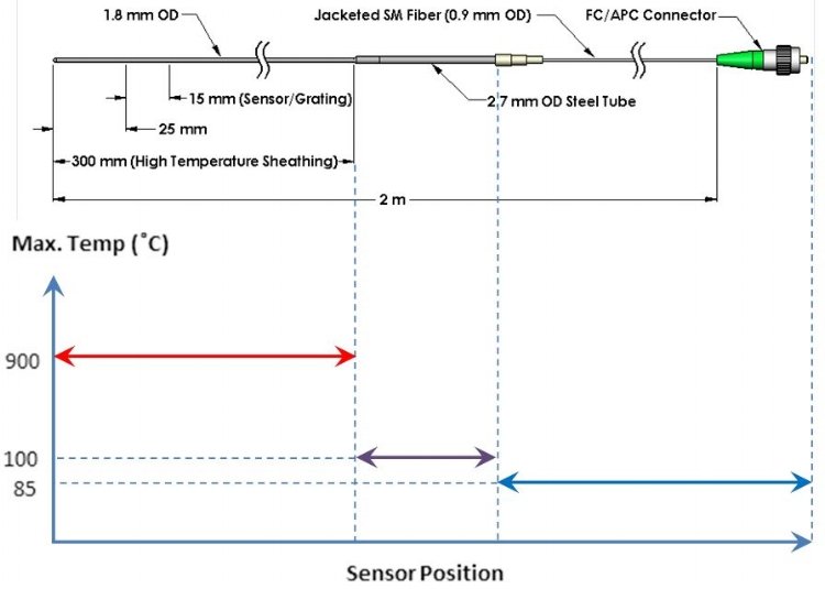
The HTS-1000 sensor enables fiber optic temperature measurements up to 900 °C with excursions to 1000 °C. In addition to the traditional benefits of fiber optic sensors, including immunity to electromagnetic interference, better environmental stability and enhanced remote sensing as compared to traditional electronic sensors, the HTS-1000 extends these benefits to ultra-high temperature applications, ranging from turbine engine test and development to refinery process monitoring and control. Microwave environments can be accommodated with an all-glass sensor housing. The HTS-1000 sensor is used in conjunction with fiber optic interrogators and is fully integrated with Micron Optics interrogators si155, and si255. The HTS-1000 is based on Chiral Photonics' chiral diffraction grating, fabricated by twisting a fiber as it is passed through a miniature heat zone to produce a distinct dip in the transmission spectrum. The spectral position of the dip in this chiral fiber changes with temperature allowing it to be used as a temperature sensor. HTS-1000 Specifications Temperature Range: Up to at least 1000 °C Accuracy: 1% Sensitivity: 0.01 nm/°C (nominal) Drift (measured over more than 1400 hours at 900 °C): 0.0005 °C/hr, (nominal) Probe (metal sheathing) Length: 300 mm standard – Other lengths and materials available upon request Sensor/Grating Length: 15 mm – Other lengths available upon request Sensor Placement: 25 mm from probe tip – Other configurations available upon request Connector Type: FC/APC – Other connectors available upon request Packaging: See Drawing – Other configurations available upon request Temperature testing was carried out in a computer-controlled high-temperature oven in which the temperature was also monitored by a thermocouple. Both long-term temperature stability and temperature sensitivity were tested using a fiber optic interrogator to monitor sensors as they were cycled from room temperature to 1000 °C. The characteristic spectral dip wavelength shifts to the red by approximately 1.3 nm as the temperature is raised by 100 °C. The figure below shows the wavelength of the transmission dip of a chiral fiber versus temperature. The temperature was cycled five times from 700 °C to 1000 °C in the course of 24 hours, dwelling for 3 hours at these temperatures. The inset shows the temperature variations. As seen in the figure below, the HTS-1000 is capable of reliably measuring temperature up to 1000 °C with better than 1% accuracy. Drift measured over more than 1400 hours at 900 °C was 0.0005 °C/hr. The sensor is recommended for continuous monitoring to 900 °C with excursion to 1000 °C.
CATEGORY
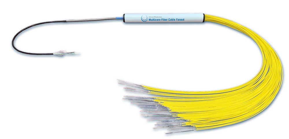
Having designed and deployed the world's first ultra-dense, 1152-channel multicore fiber (MCF) link in a metro network, [1] Chiral Photonics is excited to offer these high bandwidth density links to address your application needs. These high density cable links help reduce conduit congestion, reduce cable weight, fit into conduit space where standard cables may not and reduce cable crowding at the front panel. [1] V.I. Kopp, et. al., “Ultra-dense, 1152-core, broadband multicore fiber link deployed in a metro network,” Opt. Express 31, 5794-5800 (2023). Multicore Fiber Addresses: Conduit Congestion - Increased bandwidth in smaller cross-section cable. Excessive Cable Weight - Bandwidth capacity can be increased without taxing fiber trays and raceways Inflexible Cables - A smaller outer diameter cable, enabling higher bandwidth, has a smaller bend radius, is more flexible and can be snaked through longer and more circuitous routes. Overcrowded Equipment Front Panels - Running more bandwidth to equipment without the need to expand the equipment footprint in the rack. Among the applications that can be addressed are: Data Center Interconnects - 2 and 4-core multicore fibers, along with CPI's subsea qualified fanouts, are currently being incorporated in new subsea cables to meet the growing bandwidth needs worldwide. Aerial or Cell Tower Fiber Links - Utilizing spatial division multiplexing with multicore fibers allow for compact designs with increased capacity. Enterprise Network Inter-building Communications - Multicore fiber cables are increasingly being used to expand bandwidth capacity in smaller, more flexible cables. MCF cables can bend and fit into conduit space where conventional cables cannot. They also provide a solution for weight-restricted locations. Equipment Input/Output (I/O) - Passive PIC attach to at the chip edge allows for high data throughput utilizing minimal chip real estate, reducing energy consumption and heat emissions.
CATEGORY
