By DREEBIT GmbH
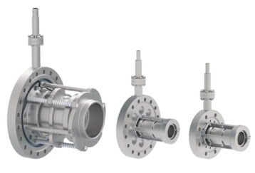
Manufacturer: DREEBIT GmbH Einzel lenses are ion optical beamline components for charged particle guiding and focusing suitable for high vacuum and ultra high vacuum environment. Each Einzel lens consists of three separated cylindrical electrodes. The central lens segment is charged with high voltage to generate the lens effect. Standard Einzel lenses are available up to a maximum high voltage of 30 kV, lenses for up to 50 kV can be developed on request. Technical Parameters Einzel Lens Parameters - inner lens diameter: 10, 20, 30, 40 mm, or customer-specific - max. lens voltage: 10, 20, 30 kV, or customer-specific General Parameters - beamline attachment flange: DN 63 CF, DN 100 CF, DN 160 CF, or customer-specific - max. bakeout temperature: 150 °C Infrastructural Requirements - vacuum conditions during operation: suitable from 1e-10 mbar up to 1e-7 mbar Scope of Delivery - Einzel lens mounted onto a CF flange of required size Optional Equipment - lens connection to electrical high voltage feedthroughs (SHV) - SHV connectors for attachment of customer supplied cables - tailored high voltage cables - power supply - vacuum chamber
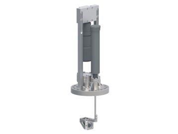
Manufacturer: DREEBIT GmbH The Beam Imaging System (BIS) allows the user to detect and evaluate particle beam cross sections in real-time in a high vacuum or ultra high vacuum environment. It creates an image of the beam by converting the incident beam signal into visible light. Description The Beam Imaging System (BIS) allows the user to detect and evaluate particle beam cross sections in real-time in a high vacuum or ultra high vacuum environment. It creates an image of the beam by converting the incident beam signal into visible light which can be monitored through the glass vacuum window. In detail, the system comprises a linear feedthrough for moving the BIS in and out of the charged particle beam axis, high voltage feedthroughs, as well as a glass viewport mounted onto a DN 100 CF support flange. The actual BIS inside the vacuum chamber consists of a chevron-type micro channel plate (MCP) for low-current signal amplification, a phosphor screen for signal conversion to visible light, a mirror, and a CCD camera including a macro zoom lens. In case medium beam intensities are to be analyzed which do not require MCP amplification, the system is delivered with the phosphor screen only. Via the CCD camera a digital image of the beam can be transferred to a PC for further analysis. The complete beam imaging system can be remote controlled which is important if access to the beamline is limited during beam operation. A control software and a PC system with the installed software are optionally available. Technical Parameters Beam Imaging System Parameters - beam current range: 0.1 pA... 500 nA - beam energy acceptance: 10... 60 keV (higher energies on request) - max. detectable beam diameter: 25 mm, 40 mm (larger diameters on request) - vertical travel: min. 50 mm (at 25 mm diameter) or 100 mm (at 40 mm diameter) (other travel distances on request) General Parameters - mounting flange: DN 100 CF - height: 480 mm - weight: 10 kg (22 lbs) - max. bakeout temperature: 150 °C Infrastructural Requirements - vacuum conditions during operation: suitable from 1e-10 mbar up to 1e-6 mbar Scope of Delivery - Beam Imaging System meter incl. manual linear motion feedthrough and tailored cables - power supplies incl. tailored cables - hardware and software for computer-based remote control and data evaluation Optional Equipment - remote controllable linear motion feedthrough - vacuum chamber with beamline connection flanges according to customer specifications
CATEGORY
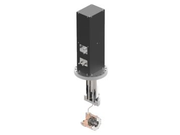
A Water Cooled Faraday Cup for High-Current Applications Manufacturer: DREEBIT GmbH This chilled Faraday cup is a device for measuring high ion beam currents. The heating power from an incident ion beam of up to 1.5 kW can be dissipated while evaluating the signal. The High-Current Faraday Cup is a device for measuring high ion beam currents. The setup contains a metal back plate which is electrically insulated towards the housing but connected to a water cooling system by a thermally conductive insulator. Thus, heating power from an incident ion beam of up to 1.5 kW can be dissipated while measuring an electrical current. Furthermore, the Faraday cup features a removable aperture plate as well as a suppressor electrode for suppression of secondary electrons emitted from the cup surfaces at ion impact. The Faraday cup is mounted on a pneumatic linear push / pull positioner on a DN 160 CF flange. The up and down position is indicated by two relay contacts. The standard travel length between both positions is 100 mm which can be adjusted to the requirements of the customer if necessary. The cup is suitable for ultra high vacuum conditions down to 1e-10 mbar. The images given in addition to the rendered picture of the complete system show a detailed view of the cup as well as a simulated heat distribution at 1 kW incident beam power. Technical Parameters Faraday Cup Parameters - aperture diameter: 40 mm or customer-specific - travel distance: 100 mm or customer-specific - recommended suppressor voltage: 200 V - max. beam power: 1.5 kW General Parameters - height above lower flange edge: 414 mm - distance lower flange edge to beam center: 353 mm - beamline attachment flange: DN 160 CF, other flange types available - weight: 18 kg (40 lbs) - current signal: BNC connector - travel end positions: 5-pole M12 connector, 2 relay contacts - max. bakeout temperature: 150 °C Infrastructural Requirements - vacuum conditions: from 1e-10 mbar up to atmospheric pressure - pneumatic push / pull positioner: dry air, 7 bar - cooling water: one circuit, 1.5 l / min at 3 bar Scope of Delivery - High-Current Faraday cup readily assembled and mounted onto a DN 160 CF flange - electrical feedthroughs - pneumatic linear push / pull positioner Optional Equipment - vacuum chamber - picoampere meter or electrometer for measurement of charged particle current or pulses - LabView based control and measurement software Downloads - ProductSheetHighCurrentFaradayCup.pdf
CATEGORY
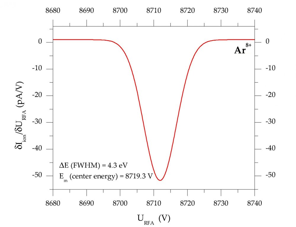
The Retarding Field Analyzer (RFA) is an electrostatic charged particle beam energy analyzer which allows for measuring the kinetic energy distribution and the energy spread of the particles. The system mainly consists of three meshes, the central one being set on high voltage to establish the retarding field, and a Faraday cup at the end detecting the beam current. Furthermore, the RFA features a collimator with changeable apertures of 1mm, 2mm, or 3mm diameter at a length of 50 mm to optimize the setup considering beam intensity versus required energy resolution. The setup can be mounted onto a linear motion feedtrough with the beam axis perpendicular to the DN 160 CF support flange normal but also at the end of a beamline directly onto a DN 100 CF flange. The maximum mesh voltage is limited to 15 kV meaning that energy distributions of particles up to 15 keV per charge state can be analyzed. Functional Principle To analyze the energy distribution of a charged particle beam the potential of the retarding field mesh is increased stepwise while measuring the beam current on the Faraday cup. While increasing the retarding field, 5 phases of influence on the incident beam can be distinguished, as summarized in Figure 1: - particles pass the mesh (retarding potential very low) - particles are focused into the mesh holes (retarding potential increased) - particles reflection begins (retarding potential reaches the range of the kinetic beam energy) - some particles are stopped, some can still pass (retarding potential is near the mean energy) - all particles are stopped (retarding potential is higher than the kinetic energy of the particles The measured dependency I ion versus U RFA can be differentiated to obtain the beam energy distribution δU ion/δI RFA which can be fitted with a Gaussian, see Figure 2. Thereby, the mean energy of the charged particles E m is defined as the maximum of the Gaussian. The energy spread of the beam is defined as the full width half maximum (FWHM) of the distribution. An example showing the possibilities of the RFA in terms of resolution and sensitivity is presented in Figure 2. The measurement was carried out using a Dresden EBIS-A producing a beam of Ar 8+ ions. In this experiment, the 3 mm collimator apertures were used. A properly adjusted high-quality ion beam from the EBIS-A does not require an additional collimation effect, thus, large apertures can be used to achieve the maximum signal intensity.
CATEGORY
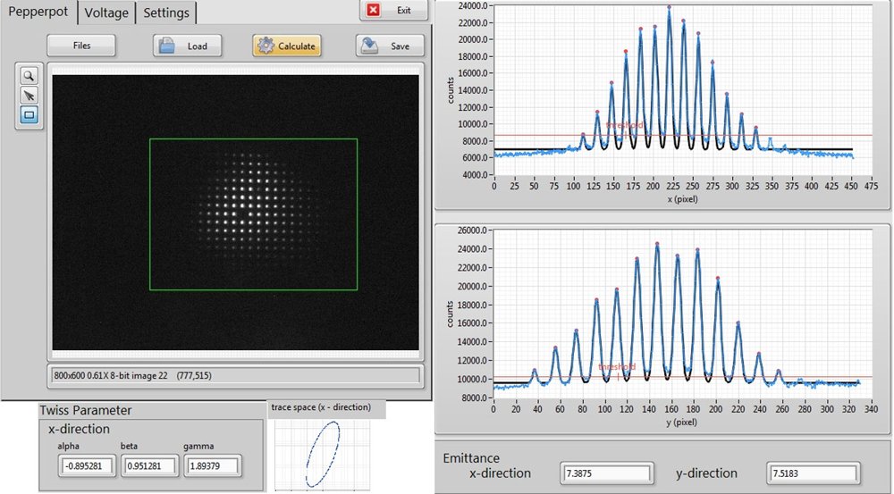
The Pepperpot Emittance Meter is an imaging system which allows for detecting and evaluating beam parameters of particles as well as x-rays in real-time. The setup is mounted onto a single DN 160 CF flange with a linear motion vacuum feedthrough, two SHV high voltage feedthroughs, a glass viewport, and a camera holder. The main components of the diagnostics unit are the pepperpot-like pinhole mask, a micro channel plate (MCP) and phosphor screen assembly, a mirror, and a CCD camera. The camera, the Pepperpot power supplies, and, optionally, also the linear feedthrough can be remote controlled which is especially important in case operators do not have access to the measurement setup during charged particle beam operation. For high-intensity beams or x-rays the imaging system can be modified according to the different requirements in these cases. For example, high-intensity beams do not demand signal amplification through an MCP system. Instead, high beam intensities may require the use of special Pepperpot mask materials or an additional shutter system with active cooling to reduce the power introduced to the Pepperpot by the incident beam. Functional Principle The functional principle of the system is based on the incident beam being separated into several beamlets by the Pepperpot mask. In case of low-intensity charged particle beams, the beamlets are converted to secondary electrons using the MCP and finally an optical image is produced by the phosphor screen. In this standard setup, the MCP-produced electrons are accelerated onto a phosphor screen producing visible light which can be monitored through the glass vacuum window. With the help of an analyzing and control software, the emittance and Twiss parameters of the beam can be calculated from the captured image. The control software of the Pepperpot system allows to adjust the high voltage for the MCP and the phosphore screen. The voltages define the amplification factor of the system. After having adjusted the voltages, the image of the ion beamlets created by the Pepperpot can be observed in real time. With an image of the beamlets taken by the CCD camera, the emittance and Twiss parameters of the incident ion beam can be calculated using the analyzing software. The software uses the x- and y-projection of the beamlets which are fitted by multiple Gaussians for the following calculations.
CATEGORY
