HPLS-35DD7500-2C HPLS-35DD7500-4C Two and Four Channel High Speed Drivers for Short Duration, Intense LED Flashes Features • Repeatable High Intensity Output driving LEDs with 7.5Amps of current for pulse width duration from <500nS to 40μS with DD7500 Driver boards. • SmartTime Time Limiting Circuitry protects LED emitters by shutting down the output if pulse width or duty cycle is exceeded. • 3% Duty Cycle • Burst mode capability The HPLS-35 series drivers provide acompact high speed driver for controlling short flashes of 2 or 4 LEDs with independent input control. Description HPLS-35-DD7500-2C HPLS-35-DD7500-4C Enable 3.5-24V Active High To LED Group Common Trigger 3.5-24V Active High Power Input HPLS-35 Pin Designation: Test 3.5-24V Active High Inputs (One Channel Shown) Output (One Channel Shown) Mating Connectors: Input Phoenix 1827729 Lightspeed PN: LT1827729 Output Phoenix 1827703 Lightspeed PN: LT1827703 Power Phoenix 1827716 Lightspeed PN: LT1827716 For Mechanical Dimensions, see.info.pdf file STEP Files Available Contact Lightspeed Technologies Specifications subject to change Mounting Options: Din Rail Mount: HPLS-35-DIN1 Flat Surface Mount (2 Brackets, black): HPLS-MB40 (40mm) or HPLS-MB80 Output Connector Cables: C-TB2-0.5M Cable - 0.5 meter length. Phoenix pluggable terminal block 2 pin connector. C-TB2-1M Cable - 1 meter length. Phoenix pluggable terminal block 2 pin connector. C-TB2-1.5M Cable - 1.5 meter length. Phoenix pluggable terminal block 2 pin connector. C-TB2-2M Cable - 2 meter length. Phoenix pluggable terminal block 2 pin connector. PIN 1234PIN 12LED NEG LED POS Applications • High-speed imaging • Synchronous detection • Machine vision • Fluorometry • Multiple Wavelength Illumination Power requirements: HPLS-35-DD7500-4C: +24V, 2A HPLS-35-DD7500-2C: +24V, 1A Pin 1: POWER COM PIN 3: GND SHIELD Pin 2: POWER +24V Mounting Configurations For Mechanical Dimensions, see.info.pdf file STEP Files Available Contact Lightspeed Technologies Specifications subject to change Din Rail Flat Surface Mounted Illuminator Options – See Separate Data Sheet • HPLS-26PX2 LED Socket with OH26 Optics Options • RS1 LED Socket with OH36 Optics Options Impact of Lead Length on Pulse Width and Current to LED Wire Length (m) 50% rise (nS) 50% fall (nS) 90% rise (nS) 90% fall (nS) 90% rise+fall (nS) Shortest Rectangular pulse 50% flat (ns) Shortest Rectangular pulse 75% flat (ns) Current (A) LED 0.0254 40 25 140 40 180 360 720 6.5 0.5 70 40 260 60 320 640 1280 61 80 45 350 100 450 900 1800 5.7 1.5 110 50 500 130 630 1260 2520 5.2 2 130 55 650 150 800 1600 3200 5 HPLS-36DD7500 Driver Board Waveforms and specifications Digital mode specifications: • Output current: 7.5A +/- 1A (LED head dependent) • Rise Time: 45ns (to 1/2 level); 117ns (to 90%) • Rise front propagation delay: 100ns +/-5 • Fall Time: 30ns (to ½ level); 45ns (to 90%) • Fall front propagation delay: 100ns +/-5 • Pulse front/fall jitter: 10ns MAX, <5ns typ • Nominal Signal Level: 3.3-5V; TTL/CMOS • Logical “0” (light OFF): <0.8V • Logical “1” (light ON): >2.4V • Smart Time Limiting Circuitry for LED Protection Limits the Cumulative Energy Delivered to LED • Single Control Pulse length range: 50ns-40us • Matching optical pulse half-width (50ns-40us) • Maximum Duty Cycle of Continuous Waveform: 3.3% • Average Ratio, Active Time/Relaxation Time: 1:50 • Any Repetition Rate Digital mode, protocol examples: • Example 1: 1us pulse produces optical pulse with matching within +/-15ns accuracy. 1 us pulse is permitted every 30us • Example 2: 100 ns starting pulse produces optical pulse with matching to +/-15ns accuracy • Example 3: 10us starting pulse produces virtually “rectangular” optical pulse • Example 4: Too long starting pulse will be cut by Time Limiting Circuitry to 40 us. • Example 5: 100ns starting pulse will produce 100 ns optical pulse with peak which is 88% of steady level observed with 1us pulse. Further shortening the pulse will lower the peak more. Example 1: 1.025us control pulse (blue), matching 1.017ns optical pulse (red) Example 4: 80us starting pulse (blue) cut to 40us optical pulse (red) by Time Limiting Circuitry Example 2: 100ns control pulse (blue); 108ns optical pulse (red) Example 3: 10 us control pulse (blue), optical pulse (red) Example 5: Illustration how the position of fall front of starting pulse (blue, violet) affects the shape of optical pulse (red, purple) Preliminary - Specifications subject to change
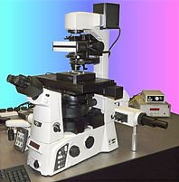
A fully functional computer controlled unit for the multiple spot trapping and manipulation of micron sized particles. It is designed to be attached to high quality commercial instruments, upgrading them to Photonic Force Microscopes, especially useful in mechanobiology experiments and biomechanics.
CATEGORY
This system is designed for single spot trapping and manipulation of micron sized particles. It is designed to be attached to a high-quality commercial instrument, converting it into a Photonic Force Microscope (PFM), especially in mechanobiology experiments and biomechanics.
CATEGORY
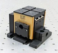
2 mm coarse travel per axis 4.5 kg load capacity Minimal arcuate displacement Orthogonal alignment grooves Use any combination of Elliot Scientific adjuster types Ultra-stable patented† design XYZ flexure stage
CATEGORY
