By Graphenea
A: GO is extensively washed and some metal traces can be found in ppb. A: The GO is a polydisperse material where most of the particles have a size around 15 μm, as shows the next results measured by laser diffraction: - D90 29.05 - 32.9 μm - D50 14.30 - 16.6 μm - D10 5.90 - 6.63 μm A: The surface area in dispersion form is not possible to measure since most techniques require the dry form and GO tends to agglomerate when water is removed. All GO surface is exposed to the water when it is in dispersion form so the surface area should be very high. The GO flakes are monolayer thick (2nm measured via AFM) in dilute dispersions. A: In general terms, the less you sonicate the dispersion the bigger the flakes are. A: Our standard dispersion has a 4 mg/mL concentration. At this concentration flakes tend to stack so in order to get monolayer flakes it would be recommendable to dilute it to 0.5 mg/mL and sonicate further. After this process 95% monolayer content can be achieved. A: The GO is inherently acidic due to the presence of acidic functional groups so the acidity is not an indication of purity or lack of it. The acidity is more related to the concentration of the GO in the water. The higher the concentration the greater the acidity. A: Our GO is dispersed in water because it is very stable and no surfactant is needed. GO is functionalized with epoxy, alcohol and COOH groups on its edges. These functional groups make GO highly hydrophilic and also it loses part of its sp2 hybridization, making GO insulating. In order to recover conductivity is has to be reduced. We can work with other solvents, please contact us to know more about it. A: The average flake size is from nm up to 10 microns A: Graphene Oxide contains oxygen functional groups (hydroxyl, carboxyl and epoxy groups) that make water dispersions very stable and no surfactants are needed. A- It has to be taken into account that the dried GO is formed with GO flakes that contain oxygen functionalities as well as intercalated water. When the material is heated with a fast ramp (>5º/min), at T between 150-180ºC the gases are released very fast and that is what makes the volume of the material to increase dramatically and to have what it seems an "explosion". However, this phenomena is not observed when heating the material at slow ramps (2º/min) as the gases are slowly released and the increase of the volume is not observed.
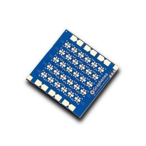
GFET GFET S-30 30 backgated graphene devices distributed in a grid pattern on the chip
CATEGORY
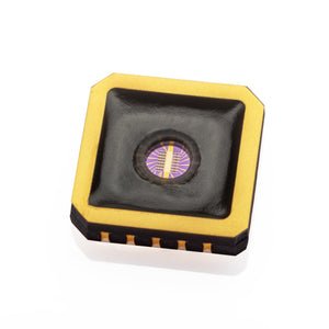
mGFET-4D (4 mm x 4 mm) - Processed in ISO 7 Cleanroom The mGFET 4x4 chip from Graphenea is designed for sensing applications, and it is compatible with measurements in a liquid medium. The metal pads are passivated to avoid degradation and reduce leakage currents. It also includes a non-encapsulated electrode at the center of the chip, which allows for liquid gating without the need of an external gate electrode (such as Ag/AgCl probes). This device architecture enhances signal-to-noise ratio and reduces parasitics. This version provides 28 graphene channels: 7 of them are one-channel devices and 7 of them are three-channel devices. These two geometries add flexibility to the measurement scheme (ΔVD or ΔIsd). The die is packaged and wirebonded to a leadless chip carrier (LCC) and it is fully compatible with the Graphenea Card Typical Specifications - · Growth method: CVD synthesis - · Graphene transfer: Polymer assisted transfer - · Substrate: Si/SiO 2 - · Substrate thickness: 525 μm - · Resistivity of Si substrate: 1-10 Ω.cm - · Metallization: 50nm Au-based Contacts - · Encapsulation: 50 nm Al 2 O 3 - · Chip dimensions: 4 mm x 4 mm - · Number of GFETs per chip: 14 - · Number of graphene channels per chip: 28 - · Optical Yield: ≥75 - · Average Dirac point (liquid gating): <1.5 V Absolute maximum ratings - · Maximum gate-source voltage (liquid gating in PBS): ± 1.5V (PBS, 0.001X) - · Maximum temperature rating: 150 °C - · Maximum drain-source current density: 10 7 A.cm -2 Quality control All our samples are subjected to a rigorous QC in order to ensure a high quality products. - · Optical Microscopy inspection of all the devices - · Raman spectroscopy of each fabrication batch - · Electrical characterisation (back gating and liquid gating) of each fabrication batch - · AFM of each fabrication batch Applications Graphene field-effect transistors (GFETs) have unprecedented sensitivity to the surrounding environment and is an ideal transducer for a variety of sensing applications. Depending on the application, mGFETs can be tuned to be sensitive only to the stimulus of interest and have shown breakthrough performance in areas such as graphene device research, chemical/gas sensing, biosensors, chemical sensors, bioelectronics, healthcare and industrial safety applications. Publications "Robust chemical analysis with graphene chemosensors and machine learning" https://doi.org/10.1038/s41586-024-08003-w Downloads - mGFET-4D Data Sheet - Measurement Protocols and Basic Handling Instructions
CATEGORY
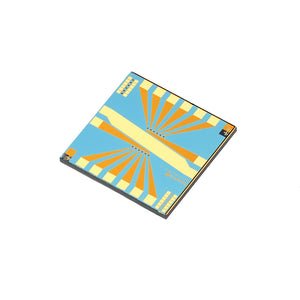
GFET-S20 (Die size 10 mm x 10 mm) - Processed in ISO 7 Cleanroom The GFET S-20 chip from Graphenea is designed for measurements in liquid medium. The new version provides 12 graphene devices, with encapsulation on the metal pads to avoid degradation and reduce leakage currents, and the probe pads located near the periphery of the chip. It also includes a non-encapsulated electrode at the center of the chip, which allows liquid gating without the need of an external gate electrode. Typical Specifications - · Growth method: CVD synthesis - · Graphene transfer: Polymer assisted transfer - · Chip dimensions: 10 mm x 10 mm - · Substrate: Si/SiO 2 - · Substrate thickness: 675 μm - · Resistivity of Si substrate: 1-10 Ω.cm - · Gate oxide thickness: 90 nm - · Metallization: 50nm Au-based Contacts - · Encapsulation: 50 nm Al 2 O 3 - · Chip dimensions: 10 mm x 10 mm - · Number of GFETs per chip: 12 - · Optical Yield: ≥75 - · Average field-effect mobility (back gating): 1000 cm 2 /V.s - · Average Dirac point (back gating): <25 V - · Average Dirac point (liquid gating): <1 V Absolute maximum ratings - · Maximum gate-source voltage (liquid gating in PBS): ± 2V - · Maximum gate-source voltage (back gating): ± 50V - · Maximum temperature rating: 150 °C - · Maximum drain-source current density: 10 7 A.cm -2 Quality control All our samples are subjected to a rigorous QC in order to ensure a high quality products. - · Optical Microscopy inspection of all the devices - · Raman spectroscopy of each fabrication batch - · Electrical characterisation (back gating and liquid gating) of each fabrication batch - · AFM of each fabrication batch Applications Graphene field-effect transistors (GFETs) have unprecedented sensitivity to the surrounding environment and is an ideal transducer for a variety of sensing applications. Depending on the application, GFETs can be tuned to be sensitive only to the stimulus of interest and have shown breakthrough performance in areas such as photosensing, magnetic sensing and biosensing. Publications "Graphene Sensor Arrays for Rapid and Accurate Detection of Pancreatic Cancer Exosomes in Patients’ Blood Plasma Samples" https://doi.org/10.1021/acsnano.3c01812 "Graphene‑based field‑effect transistors for biosensing: where is the field heading to?" https://doi.org/10.1007/s00216-023-04760-1 "Ultrasensitive detection of SARS-CoV-2 spike protein by graphene field-effect transistors" https://doi.org/10.1039/D2NR05103F "Detection of Glial Fibrillary Acidic Protein in Patient Plasma Using On-Chip Graphene Field-Effect Biosensors, in Comparison with ELISA and Single-Molecule Array" https://doi.org/10.1021/acssensors.1c02232 "Detection of an IL-6 Biomarker Using a GFET Platform Developed with a Facile Organic Solvent-Free Aptamer Immobilization Approach" DOI:10.1109/ACCES.2020.2994611 "High resolution potassium sensing with large area graphene field-effect transistors" https://doi.org/10.1016/j.snb.2019.04.032 Downloads - GFET-S20 Data Sheet download - Measurement Protocols and Basic Handling Instructions download
CATEGORY
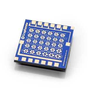
GFET-S10(Die size 10 mm x 10 mm)- Processed in ISO 7 Cleanroom The GFET-S10 chip from Graphenea provides 30 graphene devices distributed in a grid pattern on the chip. Thirty devices have a Hall-bar geometry and six have a 2-probe geometry. The Hall-bar devices can be used for Hall-bar measurements as well as 4-probe and 2-probe devices. There are varying graphene channel dimensions to allow investigation of geometry dependence on device properties. Typical Specifications · Growth method: CVD synthesis · Graphene transfer: Polymer assisted transfer · Substrate: Si/SiO 2 · Substrate thickness: 675 μm · Resistivity of Si substrate: 1-10 Ω.cm · Gate oxide thickness: 90 nm · Metallization: 50nm Au-based Contacts · Chip dimensions: 10 mm x 10 mm · Number of GFETs per chip: 30 · Optical Yield: ≥75% · Average field-effect mobility: 1000 cm2/V·s · Average Dirac point: <25 V Absolute maximum ratings · Maximum gate-source voltage (back gating): ± 50V · Maximum temperature rating: 150 °C · Maximum drain-source current density: 10 7 A.cm-2 Quality control All our samples are subjected to a rigorous QC in order to ensure a high quality products. ·Optical microscopy inspection of all the devices ·Raman Spectroscopy of each fabrication batch · Electrical characterization via back gating of each fabrication batch Applications Graphene field-effect transistors (GFETs) have unprecedented sensitivity to the surrounding environment and is an ideal transducer for a variety of sensing applications. Depending on the application, GFETs can be tuned to be sensitive only to the stimulus of interest and have shown breakthrough performance in areas such as graphene device research, quantum transport, gas sensors, chemical sensors and magnetic sensors. Publications "Graphene field effect transistors on flexible substrate: Stable process and high RF performance" DOI:10.1109/EuMIC.2016.7777516 "High-Gain Graphene Transistors with a Thin AlO x Top-Gate Oxide" Scientific Reports volume 7, Article number 2419 (2017)doi:10.1038/s41598-017-02541-2 Downloads GFET-S10 Data Sheet download Measurements Protocol and Basic Handling Instructions download
CATEGORY
