By ZAHNER-Elektrik GmbH & Co.KG
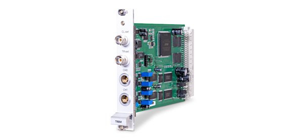
TR8M Transient Recorder TR8M CH0 TREXT CLEXT CH1 The hardware extension module TR8M for the Electrochemical Workstations IM6 and IM6e is optimized for the investigation of fast electrical events which need to be measured with a high time resolution and fixed phases in two channels. A typical application is the investigation of pulse and transient responses. As soon as the module is plugged into the IM system it is detected by the Thales software. When staring the program modules PVI, Pulse or TRC located in the Time Domain menu the programming of the transient recorder is available. In PVI and Pulse the ranges and menus are extended accordingly, in TRC parameters are input directly in the program window. The outlets for connection of the measuring signals, trigger and clock are located on the front panel of the module. On the other hand, the measuring signals may also be the potential and current channels of the IM system. These are connected internally, so that no external con-nections are necessary. For feeding external probes and instrumentation amplifiers the outlets provide a power supply of +-15V / 50mA. Installation AMOS AMOS AMOS AMOS AMOS Impedance measurement unit ZAHNER telec refe elec probe E counter electrode probe I IM6 IM6 IM6 AMOS AMOS AMOS AMOS AMOS AMOS TR8M CH0 TREXT CLEXT CH1 Disconnect the IM system as well as the PC from mains! Remove the front panel named "IM6 Extensions". Plug in the TR8M module in one of the free slots and fix it with the screws. Functional Test Connect the IM system to the mains and switch it on Press the <B> key in the startup menu to jump to the andiBASIC input window Input the following line: ST%=ink(0,hex("4600")):printST% <RETURN>-Taste A “1” must be returned for the older version of the TR8M or a “0” for the newer version In case of defect (displayed value ≠ 1): Write down the displayed value Switch off the system Contact you local Zahner representation Before you switch on the IM system again, please remove the TR8M module. Outlets TR8M CH0 TREXT CLEXT CH1 External clock (sampling clock), TTL External trigger, max. ±5 V Input channel 0: ±2 V, 10 K Ω Input channel 1: ±2 V, 10 K Ω Signal input + Power supply +15 VDC Power supply ground Signal input - Power supply -15 VDC Software Installation In case your system is not ready for the TR8M, please install the software update included. Only the the extended ranges and menus are available. Currently, the TR8M is supported by the software modules PVI, Pulse and TRC. How to install the software update please read in the IM manual. Specifications Max. sampling rate 40 MHz one channel, 20 MHz two channels Channels 2 Max. input voltage ±2 V (external), ±2 V (internal) Input impedance 10 K Ω Resolution 12 Bit Power supply outlet ±15 VDC / 0.05 A Onboard sample memory 8 MWords Trigger modes Level, slope, pre-trigger, source (internal/external) Max. trigger level ±5 V (60 Ω) Clock max. ±5 V Configuration By software Power supply +5 V / 0.55 A, +15 V / 0.07 A, -15 V / 0.1 A Dimensions 4 TE (one IM slot)
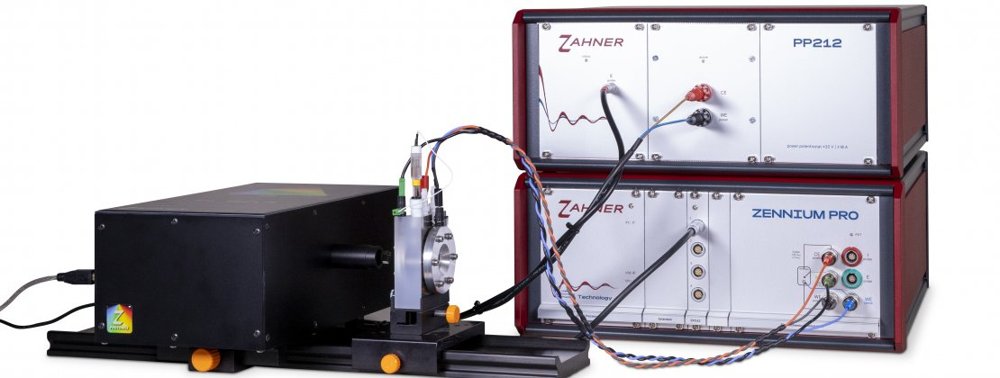
For incident photons to current efficiency (IPCE) measurements, the CIMPS system can be equipped with the CIMPS-PCS extension, including a tunable light source (TLS). The TLS makes use of an active feedback loop to ensure accurate light illumination. Equipped with up to 29 LEDs and a monochromator, the TLS provides a wavelength resolution down to 1 nm in the visible light range. The system measures the IPCE using sine-wave modulation of the light source, allowing for the measurement of true IPCE. The CIMPS system, extended with CIMPS-PCS, can also be used for standard electrochemical and photoelectrochemical techniques which are possible with the CIMPS system. Methods - Incident photon to current efficiency (IPCE) - Chopped light voltammetry (CLV) - Controlled intensity modulated photocurrent spectroscopy (controlled IMPS) - Controlled intensity modulated photovoltage spectroscopy (controlled IMVS) - Maximum power and fill factor measurements - Light transient measurements - Time domain measurements - Standard electrochemical measurements Technical specifications IPCE system ZENNIUM PRO: Max current: ±3 A Max voltage: ±5 V / ±15 V 12 current ranges for the optimum current accuracy PP212: Power potentiostat for controlling the light intensity TLS Wavelength range: 365 nm - 1020 nm IPCE-UV system Zennium Pro: Max current: ±3 A Max voltage: ±5 V / ±15 V 12 current ranges for the optimum current accuracy PP212: Power potentiostat for controlling the light intensity TLS wavelength range: 290 nm - 1020 nm
CATEGORY
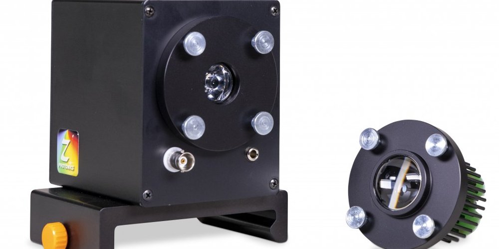
Modular LEDs (available in wavelength range: 275 nm - 1550 nm) Color | Dominant Wavelength (nm), typical | Spectral Halfwidth (nm), typical | Intensity (W/m 2), typical | Part Code Number White (3200K) | - | 500 | LSW-1 White (4300K) | - | 1000 | LSW-2 UV 275 | 14 | 30 | LS275 UV 365 | 10 | 350 | LS365-1 UV 365 | 1500 | LS365-3 UV 375 | 10 | 60 | LS375 UV 385 | 9 | 450 | LS385 UV 395 | 9 | 190 | LS395 UV 405 | 9 | 168 | LS405 435 | 30 | 170 | LS435 430 | 39 | 200 | LS430 Royal Blue 447 | 11 | 1000 | LS447 450 | 13 | 140 | LS450 Blue 470 | 17 | 600 | LS470 Cyan 505 | 19 | 340 | LS505 525 | 23 | 104 | LS525 Green 530 | 20 | 340 | LS530 565 | 25 | 2 | LS565 570 | 9 | 20 | LS570 Amber 590 | 10 | 80 | LS590 Red Orange 617 | 12 | 300 | LS617 620 | 11 | 80 | LS620 Red 627 | 10 | 30 | LS627 630 | 10 | 160 | LS630 645 | 11 | 155 | LS645 660 | 20 | 65 | LS660 670 | 15 | 105 | LS670 680 | 20 | 60 | LS680 690 | 15 | 75 | LS690 700 | 20 | - | LS700 735 | 16 | 50 | LS735 740 | 18 | 40 | LS740 750 | 30 | 75 | LS750 760 | 30 | 95 | LS760 780 | 40 | 105 | LS780 810 | 21 | 130 | LS810 850 | 25 | 200 | LS850 870 | - | 120 | LS870 IR 890 | 32 | 165 | LS890 910 | 40 | 140 | LS910 940 | 40 | 90 | LS940 950 | 30 | 160 | LS950 970 | 34 | 50 | LS970 990 | 35 | LS990 1050 | 34 | 40 | LS1050 1200 | 100 | - | LS1200 1300 | 80 | 60 | LS1300 1450 | 100 | - | LS1450 1550 | 100 | 40 | LS1550
CATEGORY
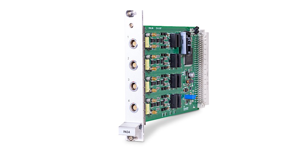
The Zahner PAD4 card provides 4 additional voltage or current input channels which can be used for parallel DC or EIS measurements on segments connected in series. The PAD4 card is an optimal addition to the ZENNIUM potentiostat for stack measurements or segmented cells. The PAD4 card is used in the fuel cell,electrolyzer stack and battery-pack investigations. In addition, it is used in measurements involving a reference electrode in a 3-electrode cell connection scheme. Parallel EIS measurements on each segment in a stack enable highly detailed measurement system behavior either in-plane or throughout the stack. Up to 17 EIS signals can be recorded in a frequency range of 10 µHz to 250 kHz. 18-bit AD converters ensure high-quality EIS data. Overview of PAD4 card variants: PAD4-HC: for investigation of individual cells in a stack of up to ±100V PAD4-LC: for investigation of segmented cells in a stack of up to ±25 V PAD4-HZ: for investigation of batteries with high-resistance reference electrodes or high-resistance objects - Parallel EIS stack measurements - Up to 17 channels for ZENNIUM X - Up to 5 channels for ZENNIUM PRO - Customizable voltage range for PAD4 channels - Incorporated with external potentiostats and electronic loads - 3 different models for stacks and segmented cells
CATEGORY