By MikroMasch
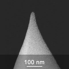
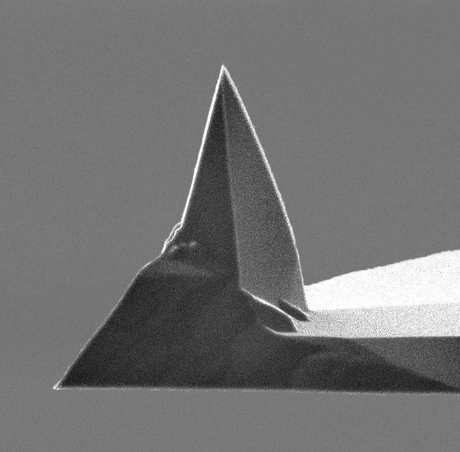
Typical radius of uncoated AFM tip 8nm Resulting AFM tip radius with the coating <20nm Full AFM tip cone angle 40° Total AFM tip height 12-18µm AFM Probe material n-type silicon AFM Tip coating Hard diamond-like carbon (DLC) Detector coating Aluminum The AFM probes in series HARD feature a 20 nm wear-resistant DLC coating applied to the tip side of the AFM cantilever. The thin DLC coating offers enhanced AFM tip durability without a significant penalty on resolution. The coating is chemically inert and more hydrophobic than silicon with a natural oxide layer. The HQ:NSC, HQ:CSC and HQ:XSC AFM tips have trihedral shape with a full cone angle of 40° and even smaller at the last 200nm of the AFM tip apex. The aluminum reflective coating enhances the laser reflectivity of the AFM cantilever by approximately 2.5 times. AFM Cantilever Series 1 AFM Cantilever Series AFM Cantilever | Resonance Frequency, kHz | Force Constant, N/m min | typical | max | min | typical | max 14 series | 110 | 160 | 220 | 1.8 | 5.0 | 13 15 series | 265 | 325 | 410 | 20 | 40 | 80 16 series | 170 | 190 | 210 | 30 | 45 | 70 17 series | 10 | 13 | 17 | 0.06 | 0.18 | 0.40 18 series | 60 | 75 | 90 | 1.2 | 2.8 | 5.5 3 AFM Cantilevers Series AFM Cantilever | Resonance Frequency, kHz | Force Constant, N/m min | typical | max | min | typical | max 35 series | Cantilever A | 130 | 205 | 290 | 2.7 | 8.9 | 24 Cantilever B | 185 | 300 | 430 | 4.8 | 16 | 44 Cantilever C | 95 | 150 | 205 | 1.7 | 5.4 | 14 36 series | Cantilever A | 30 | 90 | 160 | 0.1 | 1.0 | 4.6 Cantilever B | 45 | 130 | 240 | 0.2 | 2 | 9 Cantilever C | 25 | 65 | 115 | 0.06 | 0.6 | 2.7 4 AFM Cantilevers Series AFM Cantilever | Resonance Frequency, kHz | Force Constant, N/m min | typical | max | min | typical | max 11 series | Cantilever A | 12 | 15 | 18 | 0.1 | 0.2 | 0.4 Cantilever B | 60 | 80 | 100 | 1.1 | 2.7 | 5.6 Cantilever C | 115 | 155 | 200 | 3 | 7 | 16 Cantilever D | 250 | 350 | 465 | 17 | 42 | 90 Application HARD DLC coated AFM probes are designed for routine AFM measurements of robust samples, especially when the scan size is larger than 2µm. In large are scans the lateral resolution is of less importance compared to other characteristics of the AFM tip such as mechanical durability. Furthermore, a number of AFM applications require blunt AFM tips for quantitative measurements of various physical properties of the sample (friction, indentation, adhesion).
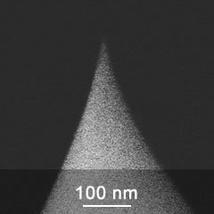
Typical radius of uncoated AFM tip 8 nm Full AFM tip cone angle 40° Total AFM tip height 12 - 18 µm AFM probe material n-type silicon AFM probe bulk resistivity 0.01 - 0.025 Ohm·cm The HQ:NSC and HQ:XSC AFM tips have trihedral shape with a full cone angle of 40° and even smaller at the last 200nm of the AFM tip apex. The soft tapping mode AFM probes feature AFM cantilevers with medium stiffness and force constants in the range 0.5-16N/m. They are used in tapping mode for imaging relatively soft samples to obtain better phase contrast and reduce surface deformations caused by the tapping AFM tip. The optional aluminum reflective coating enhances the laser reflectivity of the AFM cantilever by approximately 2.5 times. There is a range of available AFM cantilever coatings for the tip side and back side. Please check the other catalog categories for coated versions of the soft tapping mode AFM probes. The highly successful HQ series now extends over all AFM probe series with 1, 3 and 4 AFM cantilevers. 1 AFM Cantilever Series 14 series: Resonance Frequency 110 kHz min, 160 kHz typical, 220 kHz max; Force Constant 1.8 N/m min, 5.0 N/m typical, 13 N/m max 18 series: Resonance Frequency 60 kHz min, 75 kHz typical, 90 kHz max; Force Constant 1.2 N/m min, 2.8 N/m typical, 5.5 N/m max 19 series: Resonance Frequency 25 kHz min, 65 kHz typical, 120 kHz max; Force Constant 0.05 N/m min, 0.5 N/m typical, 2.3 N/m max 3 AFM Cantilevers Series 35 series, Cantilever A: Resonance Frequency 130 kHz min, 205 kHz typical, 290 kHz max; Force Constant 2.7 N/m min, 8.9 N/m typical, 24 N/m max Cantilever B: Resonance Frequency 185 kHz min, 300 kHz typical, 430 kHz max; Force Constant 4.8 N/m min, 16 N/m typical, 44 N/m max Cantilever C: Resonance Frequency 95 kHz min, 150 kHz typical, 205 kHz max; Force Constant 1.7 N/m min, 5.4 N/m typical, 14 N/m max 36 series, Cantilever A: Resonance Frequency 30 kHz min, 90 kHz typical, 160 kHz max; Force Constant 0.1 N/m min, 1.0 N/m typical, 4.6 N/m max Cantilever B: Resonance Frequency 45 kHz min, 130 kHz typical, 240 kHz max; Force Constant 0.2 N/m min, 2 N/m typical, 9 N/m max Cantilever C: Resonance Frequency 25 kHz min, 65 kHz typical, 115 kHz max; Force Constant 0.06 N/m min, 0.6 N/m typical, 2.7 N/m max 4 AFM Cantilevers Series 11 series, Cantilever A: Resonance Frequency 12 kHz min, 15 kHz typical, 18 kHz max; Force Constant 0.1 N/m min, 0.2 N/m typical, 0.4 N/m max Cantilever B: Resonance Frequency 60 kHz min, 80 kHz typical, 100 kHz max; Force Constant 1.1 N/m min, 2.7 N/m typical, 5.6 N/m max Cantilever C: Resonance Frequency 115 kHz min, 155 kHz typical, 200 kHz max; Force Constant 3 N/m min, 7 N/m typical, 16 N/m max Cantilever D: Resonance Frequency 250 kHz min, 350 kHz typical, 465 kHz max; Force Constant 17 N/m min, 42 N/m typical, 90 N/m max Application Most of the routine topography imaging experiments require AFM probes of about 8 to 10nm radius. Using these AFM probes, lateral resolution down to 5nm is attainable for scan size below 1μm. Usually, sharpened silicon etched AFM probes are used for general purpose measurements.
CATEGORY
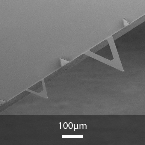
Silicon nitride XNC12 triangular AFM cantilevers Typical radius of uncoated AFM tip: 10nm Resulting AFM tip radius with the coating: 30nm Full AFM tip cone angle: 70° Total AFM tip height: 3.5nm AFM Probe material: Silicon nitride AFM Tip coating: None or Gold Detector coating: Gold The XNC12 series AFM probes have 2 different triangular silicon nitride AFM cantilevers on one side of the holder chip. The AFM cantilevers are thin and soft. Each AFM cantilever has a square pyramidal silicon nitride AFM tip with a sharpened apex. Silicon nitride AFM probes are manufactured using thin film technology. As a result, their AFM cantilevers can be thinner and with lower force constants than those made of silicon. In addition, silicon nitride is harder than silicon, offering good AFM tip durability. The AFM probes have a 70nm thick gold coating on the back side of the AFM cantilever that enhances laser reflectivity. Two options are available for the tip side of the AFM cantilevers: no coating or a 35nm thick gold coating. 2 AFM Cantilevers Series Cantilever A: Resonance Frequency typical 17 kHz; Force Constant typical 0.08 N/m Cantilever B: Resonance Frequency typical 67 kHz; Force Constant typical 0.32 N/m Application Silicon nitride AFM probes are often used for soft contact mode measurements on biological samples and other soft matter. The reflective gold coating is chemically inert and ensures stable reflectivity in liquids and buffer solutions. The optional tip side gold coating makes the AFM tip slightly rounder and more suitable for scanning extremely sensitive and tear prone surfaces such as cell membranes. It also opens the possibility for AFM tip functionalization. The XNC12 AFM probes are intended for contact mode measurements on biological and other soft samples in air and liquids. The gold coating on the detector side of the AFM cantilever ensures strong and stable reflectivity in various gaseous and liquid ambients. The uncoated AFM tips provide very good resolution, while the gold coated AFM tips offer extra protection when scanning very soft samples. In addition, gold coated AFM tips are suitable for tip functionalization.
CATEGORY
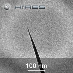
Typical spike radius 1nm Spike height 100-200nm Total AFM tip height 12-18µm AFM probe material n-type silicon AFM probe bulk resistivity 0.01-0.025 Ohm·cm AFM probe coating Gold The Hi’Res-C AFM probes have a diamond-like spike on the apex of the silicon AFM tip. The sharpness of the spike determines the resolution. The high-resolution AFM probes are recommended for scanning small areas below 250nm at 512 sampling points. Lateral resolution below 1nm is attainable. The probes feature an overall gold coating for improved laser reflectivity and chemical intertness. The diamond-like spike is not coated! AFM has become the tool of choice for non-destructive surface measurements with molecular and sub-molecular resolution. However, the resolution and accuracy of the technique is limited by the size and shape of the AFM tip. In order to increase resolution, it is necessary to decrease both the AFM tip size and the AFM tip-sample interaction force The development of the line of Hi’Res-C AFM probes has overcome these obstacles and made higher resolution, sub-nanometer imaging possible. The Hi’Res AFM probes allow for more accurate measurement of extremely narrow features such as pores, trenches, and sharp edges, along with accurate measurement of sub-nanometer surface roughness. In addition, these AFM probes are also suitable for imaging soft, fragile and near-liquid samples as the AFM tip-sample attraction force is significantly reduced due to the unsurpassed sub-nanometer AFM tip radius. Hi'Res-C AFM probes suffer less contamination than silicon SPM probes and allow obtaining many high-resolution scans when proper care is taken during use. Due to the small AFM tip curvature radius, the AFM tip-sample attraction force is minimized. The advantages of the Hi'Res-C AFM probes are noticeable when scanning smaller areas (<250nm) and flat samples. On larger images, the resolution is similar to that of general purpose AFM probes. The Hi'Res-C AFM probes are not suitable for corrugated samples.
CATEGORY
15/80/155/350 kHz 0.2/2.7/7.0/42 N/m AFM Probe with 4 Different Low Noise Conductive AFM Cantilevers AFM probes of the HQ:XSC11 series have four different AFM cantilevers, two on each side of the holder chip. They can be used in various applications. The monolithic silicon HQ AFM probes offer high consistency of the AFM tip radius, cantilever reflectivity and quality factor. The DPE AFM probes have a special structure of conductive layers applied to the tip side of the AFM cantilevers that provides a better signal-to-noise ratio in the AFM scans of electric properties. The coating thickness is increased, which gives more freedom for using the DPE AFM probes in contact electrical modes. The AFM probes provide better performance and higher contrast of electrical signals, while the ability to resolve the small surface details might be reduced. The DPE AFM probes can be used in dynamic electric modes when a study of the electric properties of a sample has higher priority. Coating: Electrically Conductive AFM Tip: Shape Rotated; Height 15 µm (12 - 18 µm); Full Cone Angle 40°; Radius < 40 nm AFM Cantilever: - Cantilever A: Shape Beam; Force Const. 0.2 N/m (0.1 - 0.4 N/m); Res. Freq. 15 kHz (12 - 18 kHz); Length 500 µm (495 - 505µm); Width 30 µm (27 - 33µm); Thickness 2.7 µm (2.2 - 3.2 µm) - Cantilever B: Shape Beam; Force Const. 2.7 N/m (1.1 - 5.6 N/m); Res. Freq. 80 kHz (60 - 100 kHz); Length 210 µm (205 - 215µm); Width 30 µm (27 - 33µm); Thickness 2.7 µm (2.2 - 3.2 µm) - Cantilever C: Shape Beam; Force Const. 7 N/m (3 - 16 N/m); Res. Freq. 155 kHz (115 - 200 kHz); Length 150 µm (145 - 155µm); Width 30 µm (27 - 33µm); Thickness 2.7 µm (2.2 - 3.2 µm) - Cantilever D: Shape Beam; Force Const. 42 N/m (17 - 90 N/m); Res. Freq. 350 kHz (250 - 465 kHz); Length 100 µm (95 - 105µm); Width 50 µm (47 - 53µm); Thickness 2.7 µm (2.2 - 3.2 µm) All typical values Packages: HQ:DPE-XSC11-15 15 pcs 490 USD; HQ:DPE-XSC11-50 50 pcs 1400 USD; HQ:DPE-XSC11-100 100 pcs 2500 USD
CATEGORY
