By Math2Market
Mat Dict is a specialized analysis module designed to extract and quantify key geometric properties of the solid phase - including material thickness, heterogeneity, particle size distribution, surface area, and connectivity. The base data: High-resolution 3D models from CT-, µCT-, FIB/SEM-scans, or geometries generated with Geo Dict. The result: A reliable assessment of the structural parameters that have a significant impact on mechanical strength, service life, and functional efficiency. Common fields of application - Battery electrodes: Structural insights to increase energy density and service life of batteries. - Fuel cells: Analysis of the gas diffusion layer for higher system efficiency. - Reservoir analysis: Reliable evaluation of complex sandstone and other reservoir rocks. - Filter media: Optimization of fabrics and nonwovens for high-performance filter systems and also technical textiles. Mat Dict provides a deep insight into the material needed to make informed decisions faster and with greater confidence, whether you are designing new materials or optimizing existing ones. Mat Dict provides multiple options to compute all relevant geometric properties of the solid material phase. The Structure Information option enables the computation of fundamental material properties, such as porosity, density, grammage, and material fractions. These calculations are performed in all three spatial directions,providing a comprehensive insight into the material's properties. Accurate Thickness Estimation is key in characterizing material microstructures and understanding their impact on performance. Advanced imaging combined with computational analysis enables precise mapping of thickness variations across a sample. This detailed measurement not only provides valuable insights for quality control but also guides material design by correlating thickness with properties such as mechanical strength and thermal behavior. The 2D Density Map option analyzes the spatial heterogeneity of materials by computing the distribution of grammage, solid volume fraction (SVF), and object count across planes in a specified direction. Each pixel in these planes represents the averaged property value along the direction of interest, providing detailed insights into variations such as cloudiness within the material. The 3D Inhomogeneity tool analyzes material heterogeneity by dividing the structure into defined sub-volumes and calculating histograms of solid volume fraction or material fraction. This provides a clear visualization of spatial variations within the material. With the option Solid Size Distribution, the solid material size distribution is characterized by fitting spheres into the solid material phase. This purely geometrical method does not distinguish between single objects / grains in the material (single grains can be identified with the module Grain Find). Computing Connected Components distinguishes separate regions within a microstructure, highlighting connectivity and isolation. This insight is vital for understanding percolation, transport behavior, and structural integrity, which helps optimize material performance. The Percolation Path option is used to calculate the maximum diameter of a spherical particle that can traverse the medium through the solid material phase and also determines the shortest path. Additionally, users can compute specific cases, such as the five largest path diameters (along with their shortest paths) or the eight shortest paths for a given path diameter.The movement of spheres along these paths is represented visually and animated. The feature Estimate Surface Area is vital for characterizing material microstructures as it quantifies the total interfacial region where key physical and chemical processes occur. This metric reveals critical information about reaction sites, diffusion paths, and interphase interactions, enabling researchers to predict and optimize material behavior in applications such as catalysis, adsorption, and energy storage. Estimate Three-Phase Contact Line is an option that allows users to identify the regions where three distinct phases converge. This analysis provides valuable insights into wetting dynamics, capillary forces, and interfacial reactivity, which are critical for optimizing processes like emulsification, catalysis, and energy conversion. Minkowski Parameters provide a robust method to quantify the geometry and topology of complex microstructures. By calculating these parameters - such as volume, surface area, curvature, and connectivity - researchers can objectively describe features otherwise difficult to characterise visually. This quantitative insight is essential to correlate microstructural characteristics with material properties. The GAD Object Orientation option is used in the computation of the orientation tensor for a given object type. With it, it is possible to check the orientation of all geometries created with Geo Dict, including those created with Grain Geo or Fiber Geo. The Chord Length Distribution (CLD) enables precise comparison of complex media geometries. Unlike traditional size distribution methods, CLD is particularly useful for 2D cross-sections where direct size measurements are impractical. By analyzing chord lengths - linear segments traversing the solid phases - it provides insights into solid connectivity, anisotropy, and heterogeneity. Geodesic Tortuosity quantifies the complexity of transport pathways in complex material geometries by measuring the ratio of the shortest actual path through the medium to the straight-line distance. It provides insights into conductivity, diffusion, and connectivity, helping to assess effective conductivity and transport efficiency. Higher tortuosity indicates more convoluted pathways, which can impede transport. The 2-Point Correlation function offers a concise statistical description of a material's microstructure by quantifying the likelihood that two points, separated by a specific distance, belong to the same phase. This measure effectively captures essential spatial patterns, aiding in the prediction of material properties and guiding the optimization of material design. The Analyze Objects feature provides a comprehensive suite of functions for the calculation of various properties, distributions and statistics of material models based on object information. This includes data analytic information from Geo Dict, as well as data derived from CT scans analysed using modules such as Grain Find and Fiber Find. These analyses yield results like contact area histograms and coordination numbers, offering insights into the interactions and connectivity within the material. Computing the Euclidean Distance Transform (EDT) for complex materials is essential for accurately characterizing their microstructure. The EDT calculates the shortest distance from any point within the pore space to the nearest solid boundary, providing a spatial map of local pore sizes. The Skeletonizer option computes the material skeleton of structures and provides a simplified representation of their complex geometry, capturing essential features such as connectivity and topology. The Compute Fractal Dimension GeoApp, for the analysis of complex materials, allows to compute the fractal dimension for a given complex structure using the box counting algorithm.
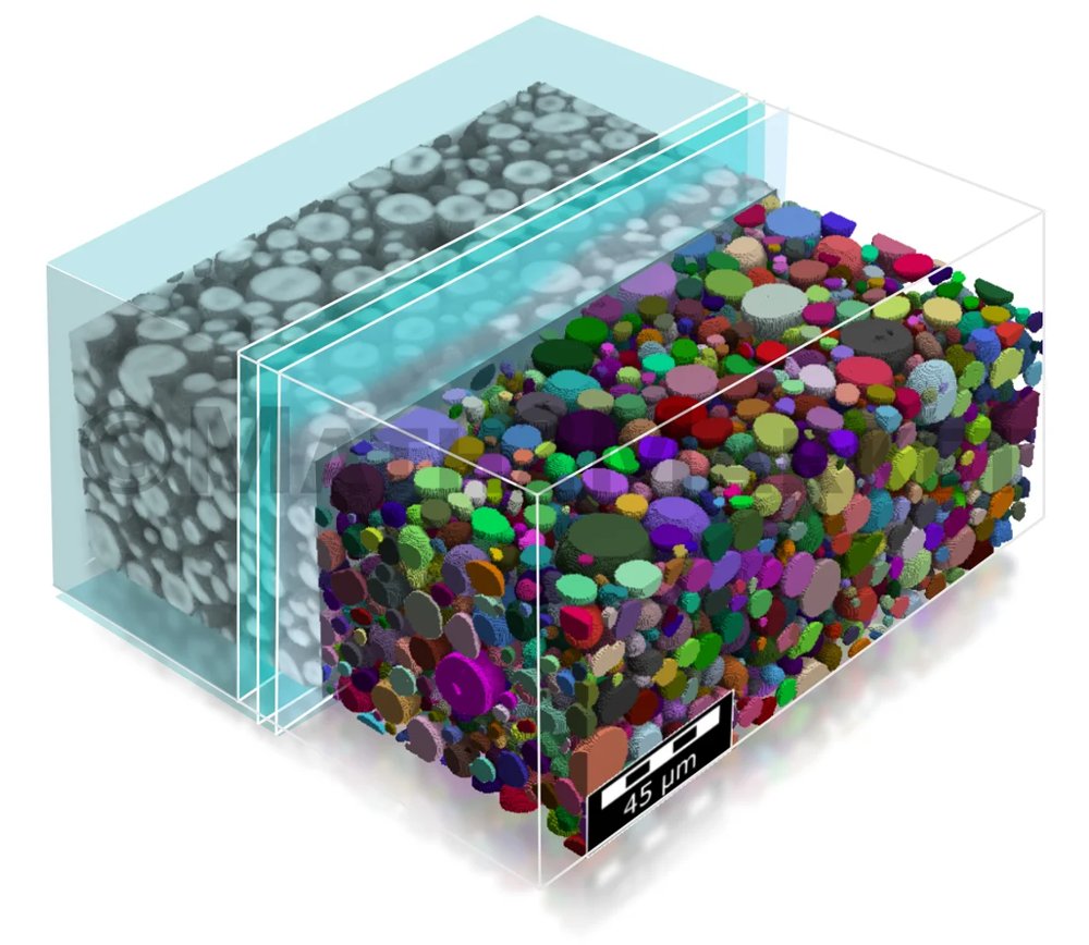
The Grain Find module provides access to statistical information of µCT-scanned granular structures, as e.g., in battery electrodes. The Identify Grains-algorithm computes an individual best-fit shape for each grain in the structure. This way, it recognizes individual grains and its spatial orientation. The acquired information can be loaded into Grain Geo with just one click to generate a representation of the microstructure. This workflow enables to model and vary statistical Digital Twins of the scanned microstructure. In µCT-scans binder and grains often have the same gray values and are thus indistinguishable from each other. For this reason, the "Identify Binder (AI)" identification module was developed. This module uses Artificial Intelligence (AI) to separate grains and binders in the solid phase based on their different shapes. Currently, Geo Dict already includes neural networks to identify the binder in NMC and graphite structures. Other neural networks for very different particle shapes or very different particle size distributions can be trained using the module Geo Dict-AI. The workflow using Grain Find-AI and Grain Geo enables simulations on the structure which would not be possible otherwise. Such as, for example, simulations of mechanical deformations, or electrode charging simulations - both depending on the distribution of the binder and sometimes even on the orientation of the grains of the active material. 3D models of a material are obtained after importing and segmenting µ-CT scans or FIB-SEM scans of this material. Grain Find offers several features to analyze this structure: - Identify and analyze individual grains: grain volume, surface, surface-to-volume ratio, sphericity (shape), orientation, etc. - Compute grain diameter distribution - Identify binder in granular structures using AI Grain identification: The grain identification process uses a specialized watershed algorithm to find individual grains, and subsequently it uses a grain reconnection to reconnect over-segmented grains. Grains on the domain boundary may optionally be removed to prevent a systematic bias in the statistics of the identified grains. Finally, a grain-shape analysis fits ellipsoids, boxes, or short fibers onto the found grains, and hence creates an analytic model for the grains. Statistical data of identified grains: Once the grains are identified as single objects, many possibilities for post processing are available, such as histograms for the diameters, volumes or surfaces of the grains. The diameter distributions, the sphericity and the other calculated parameters can also be visualized in 3D. It is also possible to sort the grains by their diameters, volumes or any other of the calculated parameters. You can even visualize each of the grains individually and for example only consider the largest grains. This allows for instance to assign different stiffnesses to the small grains, as to the intermediate-sized grains, and to the large grains. The calculated grain orientations can later also be considered in conductivity studies or during mechanical simulations. Furthermore, the results of Grain Find be used in Grain Geo to re-built this specific microstructure and make alterations to it. Binder identification (AI): The identification of binder is based on neural networks
CATEGORY
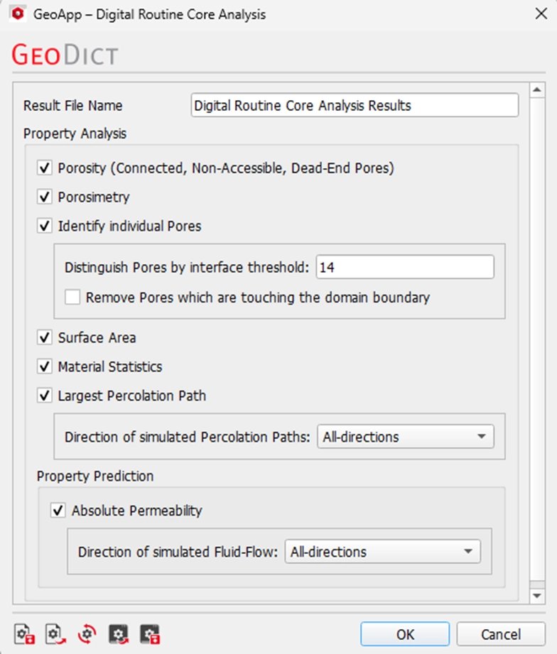
Geo Dict’s Digital Routine Core Analysis (RCA) GeoApp transforms the way you characterize core samples by providing critical insights in a fraction of the time and cost of traditional laboratory methods. It eliminates or significantly reduces destructive core testing and long lab turnaround times! High-quality results that usually take weeks of lab work are now available within hours, making Geo Dict the ideal solution for rapid core plug screening, formation evaluation, and reservoir modeling. Key features: - Automated analysis with just a few clicks: Perform complex core analyses fully automatically, without manual intervention, and with consistent, reproducible results. - Comprehensive material and structure characterization: Calculate all key material properties directly from 3D image data, for a complete understanding of the samples. - Fast and meaningful results: Obtain lab-quality insights in record time: results that would normally take weeks are available within hours. - Reports and visualizations included: Receive ready-to-use PowerPoint reports with clear simulation visualizations for internal reviews, project documentation, or regulatory submissions. - Efficiency and confidence in decision-making: Geo Dict enables confident, data-driven decisions in reservoir management, enhanced oil recovery (EOR), and formation evaluation. In a faster, more accurate, and more flexible way than ever before. Characterize porosity: Analyze the rock structure to distinguish between open and closed pores. Open pores are further classified into dead-end pores and through pores. Analyze pore space statistics: Sort pores according to their volume and gain detailed insights into the pore network. Comprehensive statistics, diagrams, and visualizations provide a clear understanding of the pore space. Predict absolute permeability: Compute permeability tensors and visualize fluid velocity and pressure fields within the rock to better understand flow behavior. Determine the percolation path in one or all directions for a complete assessment of fluid connectivity. Simulation Setup: In the intuitive graphical user interface (GUI), users can easily customize the analysis process to match their specific needs. They can select which properties to compute, define the direction of simulated flow, and even exclude pores that are in contact with the boundaries for greater flexibility and control. 1. Compute porosity to obtain detailed information about open, dead-end, through, and closed pores. 2. Utilize digital porosimetry to determine the pore throat size distribution. 3. Identify individual pores and adjust the interface threshold. If needed, exclude pores that touch the boundaries. The analysis also calculates pore volume, diameter statistics, orientation, and the number of pores and their contacts. 4. Choose whether to estimate the surface area by counting voxel surfaces and calculating the corresponding real surface area. 5. Compute material statistics to perform detailed layer analyses. 6. Determine the percolation path in any chosen direction by simulating fluid flow through the rock and visualizing its main passage. 7. Compute absolute permeability in selected directions and visualize the resulting pressure and velocity fields. A license is required for the following modules: Poro Dict, Mat Dict, Flow Dict
CATEGORY
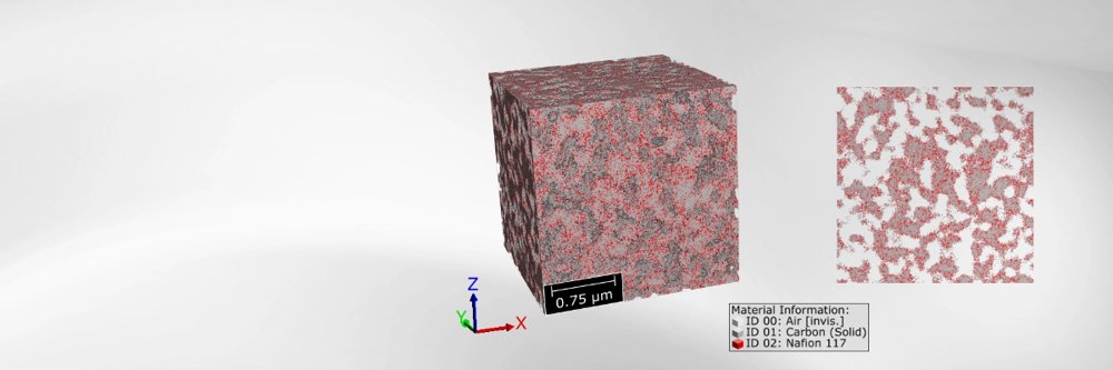
Catalyst Layers play a significant role for the performance of Proton Exchange Membrane (PEM) Fuel Cells. Their microstructure influences the electrochemical reactions as well as transport processes in the fuel cell. Due to the complex morphology of the microstructure, with nanoscale resolution, creating image data is very challenging, time intensive and expensive. Digital generation of microstructures helps to overcome this challenge. The GeoApp Catalyst Layer PEM Fuel Cell Generation offers two different approaches to generate realistic catalyst layer microstructures, consisting of carbon, ionomer and pore space. One is a parametric approach, the other one uses advanced stochastic geometric modeling. Based on user-inputs- such as voxel resolution, layer dimensions, particle content, and ionomer fraction – the GeoApp generates realistic 3D catalyst layer geometries that capture the complex morphology. The parametric approach enables the systematic creation and analysis of catalyst layer microstructures with particle packing methods, offering full control over their defining parameters. With the advanced stochastic geometric modeling approach, the GeoApp generates realistic catalyst layer microstructures from Gaussian random fields. This approach offers an advanced alternative to particle packing methods. It allows additionally to control the wetting behavior of the materials and to use different correlation functions for generating the Gaussian random fields. The predefined parameters for the random fields and the thresholding are customized for catalyst layers of PEM fuel cells. The outcome, with both approaches, are physically meaningful, fully customizable 3D structures ready for virtual testing, image analysis and multi-physics simulations to virtually evaluate the influence of microstructure variation on effective transport properties, including diffusivity, electrical conductivity and ionic conductivity. This allows targeted optimization towards one or multiple performance-relevant effective parameters. Beyond microstructural analysis, the generated ensemble of catalyst layer structures serves as a robust basis for multiscale upscaling. The computed effective properties can be transferred to larger-scale models - from 1D and 2D representations up to full 3D simulations - enabling predictive assessment of fuel cell component and stack-level performance. In this way, the application bridges the gap between microstructure design and system-level optimization, supporting data-driven development of high-performance catalyst layers. The advanced stochastic geometric modelling approach is not restricted to catalyst layers of PEM fuel cells. Similar approaches, customized for other structure types, are available in the Geo Apps Solide Oxide Electrode Generation and Solid State Battery Cathode Generation. Use cloud-based simulations to accelerate catalyst layer innovation: With Geo Dict Cloud and Massive Simultaneous Cloud Computing (MSCC), hundreds of virtual structures can be analyzed in parallel, drastically reducing time-to-insight. Catalyst Layer PEM Fuel Cell Generation with stochastic approach Example: Catalyst Layer of a PEM fuel cell with volume percentages: - Carbon particles: 50 % - Ionomer: 10 % - Pore space: 40%
CATEGORY
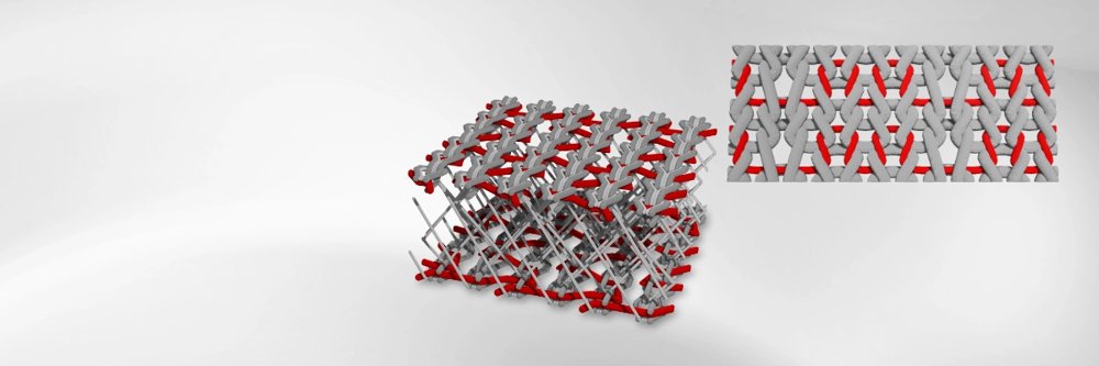
Digital Modeling of weft- and warp-knitted Textiles In addition to woven textiles, weft- and warp-knitted fabrics are used in a wide range of specialized applications, including filtration, thermal insulation, and noise reduction in the automotive, process, and energy industries. Their complex mesh structures offers a high degree of design freedom, particularly through the extension of flat textiles into three-dimensional forms such as spacer fabrics. Virtual textile design and simulation-based testing enable an efficient and resource-saving development process. As a result, the prototyping of technical weft- and warp-knitted fabrics becomes faster and more sustainable. GeoApp Features Virtual microstructure generation The TexMath GeoApp enables the generation of realistic microstructures for weft- and warp-knitted fabrics with desired dimensions and specifications. When combined with modules such as Filter Dict, Conducto Dict, or Acousto Dict, it allows the efficient calculation of the textile's filtration, insulation, and sound absorption properties, as well as targeted design optimization for specific applications, without the need for physical experiments. In addition to the fabric pattern, a range of parameters can be defined for each textile type: - Yarn diameters - Count of rows per unit length - Count of needles per unit length - Layer spacing: for multilayered textiles (e.g. spacer fabrics), the distance between individual textile layers can be defined The resulting periodic structures can be generated with any number of repetitions and at a user-defined resolution. The TexMath GeoApp allows users to easily generate a wide range of weft- and warp-knitted textile microstructures by adjusting geometric parameters. The resulting geometries range from established flat knitted fabrics to innovative three-dimensional spacer fabrics. This flexibility enables comprehensive, application-specific analysis and optimization of the microstructure of knitted textiles. Outlook: Simulation of large deformations considering yarn-yarn contacts Deformations in knitted structures are highly nonlinear. This behavior arises from the nonlinear force-strain response of the yarns and from substantial structural reorientation caused by the free sliding of yarns at contact points. The mechanical solvers in TexMath support tensile, shear, and bending simulations of the generated knitted textile microstructures. A key feature of the underlying numerical methods is the explicit representation of sliding yarn-yarn contacts, combined with efficiency gains achieved through dimensional reduction techniques. This approach enables not only the simulation of textile mechanical behavior but also couplied analyses, such as fluid flow simulations in deformed configurations. Mechanical simulations are already available in the external TexMath software and are planned for integration into future versions of the GeoApp. The following GeoDict modules are often used in combination with the TexMath GeoApp: Import & Image Processing Image Analysis Material Modeling Simulation
CATEGORY
