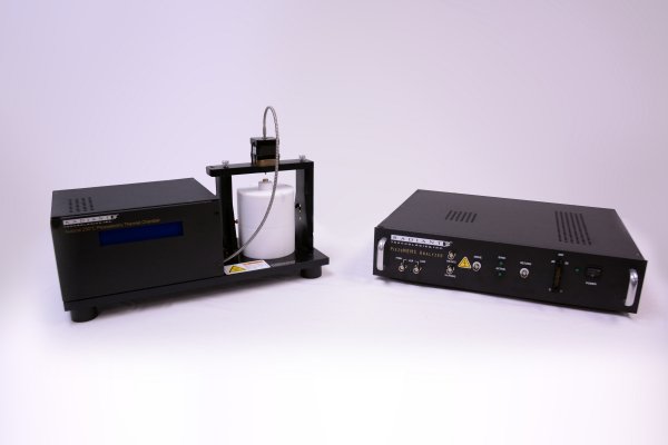
The AutoCal 230C Piezoelectric Thermal Test Chamber -The AutoCal 230°C Piezoelectric Thermal Test Chamber Includes -Displacement Sensor, Heated Piezoelectric/Pyroelectric Measurement Test Fixture, Pyroelectric/Chamber Software and Advanced Piezoelectric Software. The Self-calibration will allow fully automatic temperature (to be internally heated to 230°C) profiles for both electrical and piezoelectric tests. The heating unit is built-in to the self-contained fixture so no additional temperature chamber is necessary. The bundle's simple user interface is controlled by Radiant's fully automated Vision Data Acquisition Software. The heated test fixture provides a safe operating environment for testing at high voltages (10kV) and is rated to 230°C. The fiber optic sensor detects the amplitude of non-coherent light reflected from the sample surface to determine the distance from the sensor wand to the sample surface. The AutoCal 230°C Piezoelectric Chamber is a cost effective option for researchers measuring piezoelectric displacements on the order of one micron or larger using Radiant testers. Converse D33 Measurements are easily extracted.
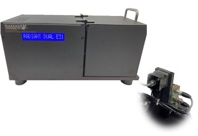
A Radiant Tester combined with the with a Dual e31 Piezoelectric Cantilever System provides a revolutionary approach to measuring both direct and converse e31 coefficients simultaneously using a single sample and test fixture. This technique reduces the need for multiple samples and fixtures, significantly improving efficiency and accuracy in piezoelectric characterization. The Dual e31 system simplifies the process by using two capacitors on a single cantilever to capture both coefficients in one test. Dual e31 Test Fixture - Built off our converse e 31 measurement system - Photonic displacement sensor self-calibrates - Five BNC connections - Four pogo pins on cantilever frontside - Fifth for cantilever backside to ground substrate - Vision controlled connection swapping in final design (Multiplexer) - Lid (not shown) reduces thermal and electrical noise Dual e31 Measurement - Apply voltage to the actuator capacitor to bend the cantilever while measuring the displacement. - Converse e31 and surface strain - Simultaneously capture the charge generated by the sense capacitor as it is bent by the actuator capacitor. - Sense polarization - Calculate the Direct e31 coefficient by dividing the surface strain into the sense polarization. - REPRODUCIBLE: No variance for re-loading same sample. - VERSATILE: Thin film or bulk, production or research. - FLEXIBLE: The Thin Film Piezoelectric Test Bundle will accommodate various sample geometries. - SIMPLE TO OPERATE Measurements with the Thin Film Piezoelectric Test Bundle Include (but are not limited to): - E31, D31, D33, E33 vs Thickness - Displacement vs voltage - Piezoelectric Fatigue - Piezoelectric Ageing - Composition Comparison - Process Monitoring - Multiple Plotting and Averaging
CATEGORY
A Laser Vibrometer attached to a Radiant Test System accurately measure the piezoelectric coefficient (d33) of thin piezoelectric films deposited on cantilevers and membranes or clamped to a substrate. Radiant's PiezoMEMS Analyzer, Multiferroic II and Precision LCII Testers use 18-bit ADC's, have 76 microvolt per bit resolution, and exhibit a noise floor of~300µV for a single pass. A Radiant Test System Combined with a Laser Interferometer can reach 0.2 Ångstrom (0.02nm) resolution in d33 piston motion. Thermal Chambers can be added to the Thin Film Piezoelectric Test Bundle to measure temperatures from-196C to 600C in a single test profile. - Laser Vibrometer with a bit resolution of 0.3 Ångstroms and bandwidth of 2 MHz. - Advanced Piezoelectric Software-Advanced piezoelectric software executes automated tests and provides clean displacement measurements for thin piezoelectric films or piezoelectric MEMs The software can be configured for different measurements and generate multiple plots at the touch of a button. It corrects multiple measurements for test stand drift and then averages/smooths the measurements to correct high and low frequency noise. - Test Stand for precise measurements.
CATEGORY
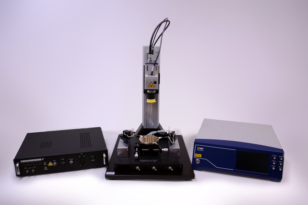
Radiant’s Precision Nano Displacement Sensor is a cost effective, compact, tabletop displacement sensor capable of measuring the surface displacements of piezoelectric thin films and the actuator displacements of piezoelectric MEMs. Derived from the extremely sensitive Atomic Force Microscope architecture, the PNDS is the inexpensive solution for measuring thin film properties. It is fully compatible with Radiant’s Vision test execution software. The PNDS provides measurement capability to sub-micron electrode dimensions with vertical resolution better than an Angstrom. Large Signal Displacement vs Hysteresis Small Signal Displacement vs Capacitance Remanent Displacement Piezoelectric Fatigue and Ageing Full Atomic Force Microscope (AFM) Capabilities Precision Nano Displacement System (PNDS) PNDS Output The PNDS output is connected to the sensor input at the rear of the Precision tester. The following measurement was taken on a Radiant Sensor Die mounted as a bender using the PNDS and a Precision Multiferroic Test System. The Y-axis is in Ångstroms. Electrical Probe The PNDS includes an electrical probe that is used as a secondary contact for energizing specimens held in the PNDS. The electrical probe includes micrometer positioning accuracies in the X, Y, and Z axis. Radiant’s Advanced Piezo Task Software is bundled with the Precision Nano Displacement System (PNDS) to measure large signal displacement vs. polarization as the sample is stimulated by tester. The Advanced Piezo Task will acquire multiple loops under automated control, remove vertical chuck drift from the measurements, average the loops, and smooth the results. The PNDS is designed specifically for use with piezoelectric thin films and provides the capability to measure displacement even on simple capacitors with shadow-masked electrodes! Features of Piezo task software Electrical probe for making contact to electrodes Cantilever/probe for measuring displacement The PNDS stage has excellent thermal and mechanical stability required for high resolution AFM scanning. Additionally, its open design facilitates user modification. Rigid Frame Design The crossed beam design for the stage support is extremely rigid so the AFM is less susceptible to external vibrations. Light Lever AFM Displacement Sensor Light lever Displacement Sensor are used in almost all atomic force microscopes and permit many types of experiments. Integrated Probe Holder/Probe Exchanger A unique probe holder and clipping mechanism allows quick and easy probe exchange. Direct Drive Z stage A linear motion stage is used to move the probe in a perpendicular motion to the sample. Probe/sample angle alignment is not required, facilitating a much faster probe approach. Small Footprint The stage dimensions of 7.5 X 12” require little space and fit easily on a tabletop. Precision XY Stage with Micrometer The sample is moved relative to the probe with a precision xy micrometer stage. Thus, the sample can be moved without touching it. Modes Electric Plug A six pole electrical plug is located at the back of the stage to expand the capabilities of the PNDS. XYZ Precision Piezo Scanner The modified tripod design utilizes temperature compensated strain gauges which assure accurate measurements from images. Also, with this design it is possible to rapidly zoom into a feature visualized in an image. Laser/Detector Alignment Both the light lever laser and the photo detector adjustment mechanism may be directly viewed. This feature simplifies the laser/detector alignment. Adaptable Sample Holder At the top of the XYZ scanner is a removable cap that holds the sample. The cap can be modified - or a new cap can be designed – to hold many types of samples. stage High resolution video microscope Direct drive Z motor stage Light lever Displacement Sensor XYZ linearized piezo scanner XY sample translation stage XYZ electrical probe translator Electronics in the PNDS are constructed around industry standard USB data acquisition electronics. The critical functions, such as xy scanning, are optimized with a 24 bit digital to analog converter. With the analog z feedback loop, the highest fidelity scanning is possible. Vibrating mode scanning is possible with both phase and amplitude feedback using the high sensitivity phase detection electronics. 24 bit scan DAC Scanning waveforms for generating precision motion in the X-Y axis with the piezo scanners are created with 24 bit DACS driven by a 32 bit micro controller. With 24 bit scanning, the highest resolution AFM images may be measured. Feedback control using the xy strain gauges assures accurate tracking of the probe over the surface. Phase and Amplitude Detector Circuit Phase and amplitude in the Ebox are measured with highly stable phase and amplitude chips. The system can be configured to feed back on either phase or amplitude when scanning in vibrating mode. Signal Accessible At the rear of the eBox is a 50 pin ribbon cable that gives access to all of the primary electronic signals without having to open the eBox. Status Lights At the front of the Ebox is a light panel that has 7 lights. In the unlikely event of a circuit failure, these lights are used for determining the status of the Ebox power supplies. Precision Analog Feedback Feedback from the light lever force sensor to the Z piezoceramic is made using a precision analog feedback circuit. The position of the probe may be fixed in the vertical direction with a sample-and-hold circuit. Variable Gain High Voltage Piezo Drivers An improved signal to noise ratio, as well as extremely small scan ranges are possible with the variable gain high voltage piezo drivers. ebox Microprocessor for scan generation through 24 bit DAC’s Low noise, variable gain high voltage amplifiers with PID feedback for XY scanning Dimensions: Width 6” | Height 10” | Depth 14” High fidelity, low noise z feedback circuits for accurate probe tracking Phase and amplitude detection circuits for vibrating mode AFM Industry standard National Instruments USB data acquisition board Internally accessible header for signal input/output Eight channels of ADC for monitoring and displaying data with LabView software Software for acquiring images is designed with the industry standard LabView™ programming visual interface instrument design environment. There are many standard functions, including setting scanning parameters, probe approach, frequency tuning, and displaying images in real time. LabView™ facilitates rapid development for those users seeking to enhance the software with additional special features. LabView also enables the PNDS to be readily combined with any other instrument using LabView VI. Pre-scan Window A pre-scan window includes all of the functions that are required before a scan is started. The functions are presented in a logical sequence on the screen. Scan Window Once all of the steps in the pre-scan window are completed, the scan window is used for measuring images. Scan parameter, Z feedback parameters, and image view functions may be changed with dialogs on this screen. LabVIEW Window Industry standard programming environment. Readily customized and modified for specialized applications. Instrumentation already using Labview can be added to the PNDS to create new capabilities. software Included with the PNDS is the Gwyddion open source SPM image analysis software. This complete image analysis package has all the software functions necessary to process, analyze and display SPM images. » visualization: false color representation with different types of mapping » shaded, logarithmic, gradient- and edge-detected, local contrast representation, Canny lines » OpenGL 3D data display: false color or material representation » easily editable color maps and OpenGL materials » basic operations: rotation, flipping, inversion, data arithmetic, crop, resampling » leveling: plane leveling, profiles leveling, three-point leveling, facet leveling, polynomial background removal, leveling along user-defined lines » value reading, distance and angle measurement » profiles: profile extraction, measuring distances in profile graph, profile export » filtering: mean, median, conservative denoise, Kuwahara, minimum, maximum, checker pattern removal » general convolution filter with user-defined kernel » statistical functions: Ra, RMS, projected and surface area, inclination, histograms, 1D and 2D correlation functions, PSDF, 1D and 2D angular distributions, Minkowski functionals, facet orientation analysis » statistical quantities calculated from area under arbitrary mask » row/column statistical quantities plots » ISO roughness parameter evaluation » grains: threshold marking and un-marking, watershed marking » grain statistics: overall and distributions of size, height, area, volume, boundary length, bounding dimensions » integral transforms: 2D FFT, 2D continuous wavelet transform (CWT), 2D discrete wavelet transform (DWT), wavelet anisotropy detection » fractal dimension analysis » data correction: spot remove, outlier marking, scar marking, several line correction methods (median, modus) » removal of data under arbitrary mask using Laplace or fractal interpolation » automatic xy plane rotation correction » arbitrary polynomial deformation on xy plane » 1D and 2D FFT filtering » fast scan axis drift correction » mask editing: adding, removing or intersecting with rectangles and ellipses, inversion, extraction, expansion, shrinking » simple graph function fitting, critical dimension determination » force-distance curve fitting » axes scale calibration » merging and immersion of images » tip modeling, blind estimation, dilation and erosion image analysis software A video optical microscope in an AFM serves three functions: aligning the laser onto the cantilever in the light lever AFM, locating surface features for scanning, and facilitating probe approach. The PNDS includes a high performance video optical microscope along with a 3 mega pixel ccd camera, light source, microscope stand, and Windows software for displaying images. Video microscope Video microscope used to locate surface features for scanning. The Vibrating Mode Cantilever is 125 μ long. Laser alignment is greatly facilitated with the video optical microscope. This non-vibrating cantilever is 450 μ long. The red spot is from the laser reflecting off the cantilever. The PNDS utilizes a unique probe holder/exchange mechanism. Probes are held in place with a spring device that mates with a probe exchange tool. With the probe exchange tool, changing probes takes only a few minutes. Probe Holder/exchange Probe Holder Probe Exchange Tool Probe Inserted in Clip 40 X 40 μ - Bacteria 30 X 30 μ Spores 7 X 7 μ - Defect 5 X 5 μ - Terraces 1 X 1 μ - 278 nm test pattern 3 X 3 μ – Phase Image MEMS Multiple Level Gear 2 X 2 μ - Si atomic terrace 10 X 10 μ - Scratch in metal 2 X 2 μ - BOPP polymer fiber 40 X 40 μ – Test Pattern Test Pattern with defect 4 X 4 μ -17 nm nanoparticles 25 X 25 μ - parasites 300 X 300 nm -Phase PMMA An open design is at the core of all products offered by the Radiant Technologies. New types of experiments are more readily designed and implemented through the use of Lab View software. All the mechanical drawings for the PNDS are available in the documentation package option. Finally, the company’s website offers a Users Forum to directly share specialized designs developed for the PNDS. For specialized applications, other types of scanners such as flexure and tubes can be easily added to the microscope stage. open design With a vertical noise floor of 0.1 nm and a horizontal resolution of 2 nm, most types of samples may be imaged with the PNDS. These include hard as well as soft samples. PNDS images Standard with every PNDS are non-vibrating(NV) mode and vibrating(V) modes for making topography scans. Additional modes included with the product are lateral force imaging as well as phase mode imaging. All of the scanning modes that can be implemented with a light lever AFM are possible with the PNDS. Although the PNDS comes with everything you need to make AFM images, several options are currently available. scanning modes PNDS options With the window below, the resonance frequency of a cantilever is readily measured. Additionally, the phase characteristics of the probe sample interaction are captured. Radiant Technologies regularly develops new Options. Contact Radiant Technologies for more information on options for the PNDS. Environmental Cell Permits scanning in inert environments or liquids. Scanner Fabrication Tool Facilitates scanner fabrication. High Resolution Scanner Allows a range of 15 X 15 microns in XY and 7 microns in Z. Vibration Cabinet Reduces unwanted acoustic and structural vibrations. Conductive AFM Measures the 2-D conductivity of sample surfaces. 15 micron scanner Environmental Cell Specifications Optional 50 Micron xyz Scanner » Type Modified tripod » XY Linearity < 1% » XY Range 50 μ » XY resolution < 10 nm closed loop < 1 nm open loop » XY Actuator type Piezo » Sensor type Strain Gauge » Z Range 16 μ » Z Linearity < 5 % » Z sensor noise < 5 nm » Z feedback noise < 0.2 nm » Z Actuator Type Piezo » Z Sensor type Strain Gauge Optional 15 Micron xyz Scanner » Type Modified tripod » XY Linearity < 1% » XY Range 15 μ » XY resolution < 3 nm closed loop < 0.3 nm open loop » XY Actuator type Piezo » Sensor type Strain Gauge » Z Range 7 μ » Z Linearity < 5 % » Z sensor noise < 5 nm » Z feedback noise < 0.1 nm » Z Actuator Type Piezo » Z Sensor type None Sample Holder » Type Magnet » Max Lateral Dimensions 1 inch » Max. Height 0.25 inch Light Lever AFM Force Sensor » Probe Types Industry standard » Probe insertion Manual – probe exchange tool » Probe holding mechanism Clip Vibrating mode piezo Electrical connector to probe » Laser/Detector adjustment range +/- 1.5 mm » Adjustment resolution 1 micron » Minimum Probe to Objective 25 mm » Laser Type 670 nm diode, < 5 mw » Detector Type 4 quadrant Band Width 500 kHz Signals Transmitted TL, BL, TR, BR Gain Lo, High Settings » Probe sample angle 10 degrees Standard XY Translator » Range 25.4 mm » Resolution 2 μ » Type Bearing - spring loaded » Lock Down Yes Z Motion » Type Direct Drive » Range 25 mm » Drive Type Stepper Motor » Min. Step Size 330 nm » Slew Rate 8 mm/minute » Limit Switch Top, Bottom » Control Software – rate, step size Digital Data Input Output » Connection USB » Scanning DAC Number 2 Bits 24 Frequency 7 kHz » Control DAC Number 2 Bits 14 Frequency 2 kHz » ADC Number 8 Bits 14 Frequency 48 kHz Analog Electronics » Vibrating Mode Freq Range 2 kHz – 800 kHz Output Voltage 10 Vpp Demod. Freq TBD » Z Feedback Type PID Bandwidth 3 kHz Sample Hold Yes Voltage 0-150 V » XY Scan Voltage 0 – 150 V bandwidth 200 Hz Pan & Zoom 22 Bits » Tip Approach Cutoff 20 μ sec. Continued Software » Environment Lab View » Operating System Windows 7 » Image Acquisition Real Time Display (2 of 8 channels) » Control Parameters PID Yes Setpoint Yes Range Yes Scan Rate Yes Image Rotate 0 and 90 degrees » Laser Align Yes » Vibrating Freq. Display Yes » Force Distance Yes » Tip Approach Yes » Oscilloscope Yes » Image Store Format Industry Standard » Image Pixels 16 X 16 to 1024 X 1024 » H.V. Gain Control XY and Z » Real time display Line Level, Light Shaded, Grey Color Pallet » Calibration System Window » Probe Center Yes » Video Microscope » Computer Industry Standard Computer Tests that may be performed on thin films in place » 1. All ferroelectric tests in Vision » 2. Piezoelectric displacement » 3. Device sorting » 4. pMEMs reliability » 5. Memory effects in pMEMs » 6. bulk sample d31 Z Noise performance depends greatly on the environment the PNDS is used in. Best Z noise performance is obtained in a vibration free environment. Every effort is made to present accurate specifications, however, due to circumstances out of the Radiant Technologies control specifications are subject to change. Field of view Resolution Working Distance Magnification Minimum Zoom 2 X 2 mm 20 μ 114 mm 45 X Maximum Zoom 300 X 300 u 2 μ 114 mm 400X Specifications
CATEGORY
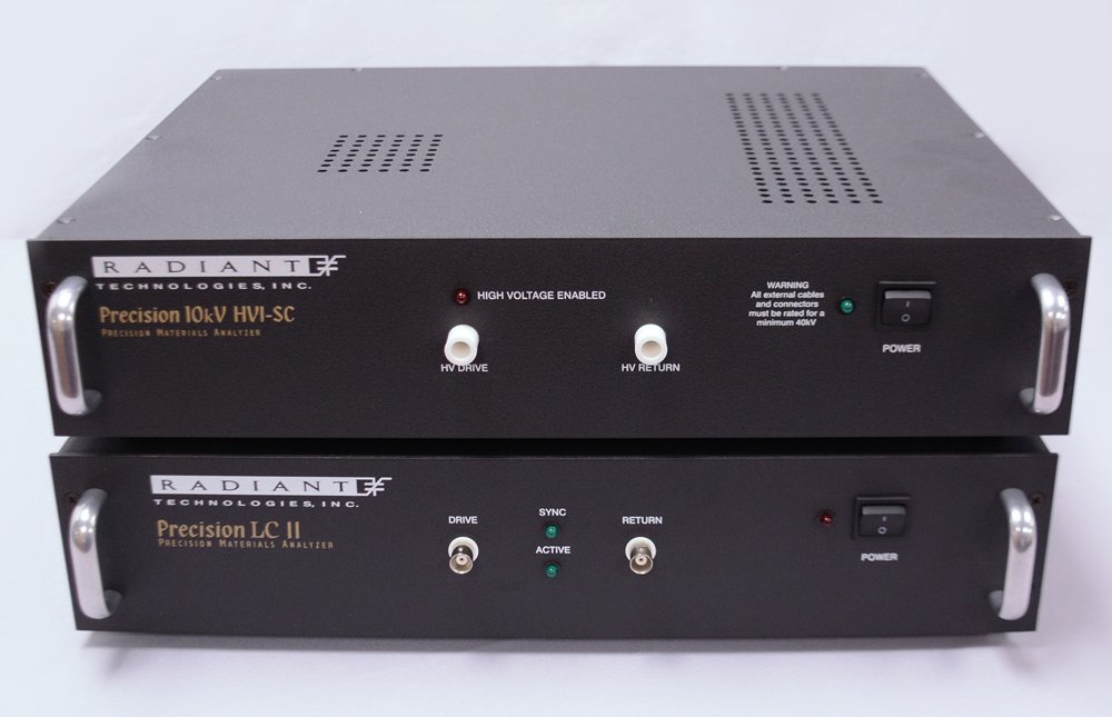
Image of a rack containing a Radiant Technologies Precision Premier II (bottom), a Radiant Technologies High Voltage Interface (middle), and a Trek Model 609B Amplifier (top) The Precision test system line can be expanded to execute tests at voltages to 10kV. Testing up to 4kV and 10kV requires a High Voltage Interface and High Voltage Amplifier. Radiant's 10kV High Voltage Interface (HVI) provides four levels of protection to the user from the high voltages present during test. The HVI has two primary functions. First, it acts as a signal router, sending stimulation voltages from the tester to the HVA while connecting the output of the HVA to the sample. The return signal from the sample is also routed through the HVI on its way back to the tester for analysis. The second primary function of the HVI is to provide protection to the user from the high voltages present during and after tests. The maximum voltage rating for the Precision High Voltage Interface is 10KV. High Voltage Interface (1) pdf Precision 10KV High Volgate Interface Specifications
CATEGORY
