HPLS 36ADxx/DDxx/APxx/A The DRAGON series High Power LED Light Sources Base unit with specific functionality LED Heads Optics Typical system configuration Features • Plug and play frame for LEDs • Interchangeable LED heads • 455nm, 475nm, 505nm, 530nm, 590nm, 617nm, 630nm, white 5500 K, white 3300 K • Selection of collimating optics/ attachments • Selection of base units • Fast analog control • Low noise CW control • Fast pulsed (digital) control • Narrow bandwidth or broadband • Wide field or focused output • Continuous, waveforms, or pulses to <150ns • Up to 400mW CW, x5 intensity short pulse The HPLS 36 series of high power LED light sources are designed as flexible system of interchangeable components for applications where it is hard to standardize the requirements for mass production. Building a system comes down to (1) selection of appropriate base with specific functionality and type of control; (2) selection of LED head[s] and (3) focusing optics specific for the application. Functionality of base units include fast analog control (to generate any optical function, sine, saw, square, CW…); low noise CW control (for applications where ATC like or PWM algorithms may cause problem); and fast pulsed (digital) control (faster and more powerful then analog). Selection of the way the optical power is set include external digital/analog signal supplied thru connector (BNC/Twin BNC), or, for CW application, Built In Potentiometer/ Remote Potentiometer/ 2 level Switch). LED heads are currently available in two form factors: LEDHRxxx series, pre collimated with build in reflector and 1.2” pin spacing for close range illumination, and LEDHxxx series with 0.8” pin spacing for higher performance and wider selection of focusing optics. Many other models of LEDs can be adapted. The function of focusing optics is to direct the light to the certain spot size on certain distance as required and often custom designed for specific application. Most of new optics is backward compatible (fits the units previously shipped) Description Applications • Plug and play frame for LEDs • Interchangeable LED heads provided • 455nm, 475nm, 505nm, 530nm, 590nm, 617nm, 630nm, white 5500 K, white 3300 K • Selection of collimating optics/ attachments • Selection of base units • Fast analog control (some models) • Low noise CW control (some models) • Fast pulsed (digital) control (some models) • Narrow bandwidth or broadband • Wide field or focused output • Continuous, waveforms, or pulses to <150ns • Up to 400mW CW, x5 intensity short pulse • Accepts LEDs with 0.2”, 0.4”, 0.6”, 0.8”, 1”, 1.2” pin spacing • Mounting to standard and metric posts (8 32 and M4x0.75 threads in base unit) • Base unit diameter 1.450” (36.8mm) • Fluorescence excitation • High speed imaging • Synchronous detection • Machine vision • Biomedical optics Base Units Ordering information Base unit with built in low noise linear driver and manual analog control. Current 0 750mA/0 1A specify. Two operating modes, selectable by the switch on control panel: fixed maximum power or adjustable by potentiometer knob. Switch momentarily between 2 levels. Easy to change LED heads, 7 different colors and 2 shades of white. Accepts LED heads with 0.2 1.2 inch pin spacing. (LEDH, LEDHR). Power requirements: 4.5 5 V, 1A (included) Power connector: 4.5 5V/1A Potentiometer: current adjust Switch: power Adj OFF Max CW, with build in potentiometer HPLS 36 AP(750, 1000) Base unit with built in low noise linear driver and manual analog control. Current 0 750mA/0 1A specify. Two operating modes, selectable by the switch on control panel: fixed maximum power or adjustable by potentiometer knob. Switch momentarily between 2 levels. Easy to change LED heads, 7 different colors and 2 shades of white. Accepts LED heads with 0.2 1.2 inch pin spacing. (LEDH, LEDHR). Power requirements: 4.5 5 V, 1A. Power connector: 4.5 5V/1A Signal Connector: ext pot/signal Switch: power Adj OFF Max CW, with remote potentiometer HPLS 36 AR(750, 1000) Base unit with built in low noise linear driver and 2 level power control by the ON OFF ON switch on the control panel. Suffix 750/1000 specify. Current levels: 500, 750 mA for model with suffix "750". Currents of 500mA, 1000mA for model with suffix "1000". Switch momentarily between 2 levels. Easy to change LED heads, 7 different colors and 2 shades of white. Accepts LED heads with 0.2 1.2 inch pin spacing. (LEDH, LEDHR). Power requirements: 4.5 5 V, 1A (included) Power connector: 4.5 5V/1A Blank plug Switch: power 1 OFF 2 CW, two level control HPLS 36 AT(750, 1000) Base unit with built in 7.5A driver for applications where faster fall/rise time, short pulses at low duty cycle are required. Light is triggered by external signal, TTL/CMOS 3 5V, BNC connector, 117ns rise time, 45ns fall time. Optical pulse half width matching the half width of starting pulse. Smart Time Limiting circuitry limits cumulative energy delivered to LED. Single pulse length range 50ns 40us, maximum duty cycle of pulse train 3.3%, average active/relaxation time ratio is 50:1. Any repetition rate. Power connector: 24V/0.5A Signal connector: Digital input Switch: Aim 0 OFF 1 faster rise time, higher intensity HPLS 36 DD7500 Same as HPLS 36AD3500 but Dual Inputs for simultaneous Analog and Digital Control. Twin BNC connector. Test mode for aiming. Twin BNC cable, power supply included Power connector: 12V/1.0A Signal connector: A&D input Switch: Aim 0 OFF 1 dual input variant HPLS 36 AD3500DI Base unit with built in driver, for high current at low duty cycle/ pulse busts app. Analog mode (500mA) or digital mode (3.5A), selectable by switch on control panel. Accepts LED heads with 0.2 1.2 inch pin spacing. (LEDH, LEDHR) Digital mode: light is triggered by external signal, TTL/CMOS input 3V 5V, BNC connector; 150 ns rise time, 200ns fall time; Smart Time Limiting circuitry limits cumulative energy delivered to LED for protection. Single pulse length range: 0.5us 1 ms, maximum duty cycle of pulse train is 10%, average active time/relaxation time ratio is 1:10. Any repetition rate. Analog mode: optical output is proportional to the analog signal applied, <2us stab time, selectable format 0 5V, 0 10 V, 4 20mA, 0 20mA. Power requirements: 12V, 0.5A (included) Power connector: 12V/1.0A Signal connector: A/D input Switch: mode D OFF A 500mA analog 3500mA digital driver HPLS 36 AD3500 Base unit built in 500mA driver. Analog or digital mode, selectable by switch on control panel. Accepts LED heads with 0.2 1.2 inch pin spacing. (LEDH, LEDHR) Digital mode: light is triggered by external signal, TTL/CMOS input 3V 5V, BNC connector; 150 ns rise time, 200ns fall time; from 300ns pulses to CW, any repetition rate. Analog mode: optical output is proportional to the analog signal applied, <2us stab time, selectable format 0 5V, 0 10V, 4 20mA, 0 20mA. Power requirements: 12V, 0.5A. Power connector: 12V/0.5A Signal connector: A/D input Switch: mode D OFF A 500mA analog/digital driver HPLS 36 AD500 Base unit with built in 500mA "digital" (triggered) driver for PWM/triggering, any duty cycle up to CW. Accepts LED heads with 0.2 1.2 inch pin spacing. (LEDH, LEDHR) Driver: build in, light is triggered by external signal, TTL/CMOS input 3V 5V, BNC connector. 150 ns rise time, 200ns fall time. From 300ns pulses to CW, any repetition rate. Power requirements: 12V, 0.5A. Power connector: 12V 500mA Signal connector: Digital input Switch: Aim 1 OFF ON 500mA digital driver HPLS 36 DD500 Detailed description Functionality and controls Brief description Model Base Unit HPLS 36AD3500 Description HPLS Base Unit with built in 2 channel driver. Analog channel has linear control and continuously variable output, with 1% input offset to ensure shutdown when signal is not applied. Digital channel has 2 level ON OFF control (active HI). Output current in the sum of outputs of both channels. Switch on the control panel selects which channel is addressed by input BNC connector, thus selecting Digital or Analog mode. There is an important difference between the output stages of Analog and Digital channels. Analog channel operates in current regulation mode using a feedback from the current sensor in the output stage. Digital channel, on the other hand, provides fast switching while the current is limited by the resistor (without active feedback). This is because the channels are optimized for different purposes: Analog channel is designed to convert the input voltage into output current as precisely as possible and as fast as reasonable but not to hurt the precision; while Digital is optimized for switching the current to MAX level and back to 0 as fast as possible. As a side effect, the current in Digital mode varies slightly for different LED head; while the Analog channel current is regulated to be the same. Base unit accepts LED heads with 0.2 1.2 inch pin spacing. (LEDH, LEDHR). Accepts focusing optics and attachments mounted on LED head directly and models that have index “36” in a part number. Common Specifications • Two operating modes: Analog/Digital • Dimensions: Ø1.45x4.5” (36.8x115mm) • Weight: 0.66 lb (0.3 kg) • Power Requirement: 12V, 0.5A • Power Connector: 5.5/2.1 mm Power Jack, center positive, barrel common ground • Control Signal Connector: BNC • Thermal resistance, convection: 5 C/Watt Absolute Maximum Ratings • Power Input: 1 to 14V; 2 A to 2A; fuse protected (2A) • Signal Input, Digital Mode: 2.5V to 7V; 50mA max, 50 Ohm input impedance • Input, Analog Mode: 1 0V to 20V HPLS 36AD3500 exterior view, dimensions and mounting interface. HPLS 36AD3500 control panel: Switch function: mode selection • Left: Digital mode • Center: OFF • Right: Analog mode BNC connector: • Central pin: input signal • Barrel: common ground LED: input power indicator LED head connector: • 13 pins x 0.1” pitch • Pins 1 6, marked red or yellow: positive • Pin 7: NC • Pins 8 13: negative • Accepts 0.025” (0.64m) square pins, 0.230” long 1 13 Digital channel Analog channel Linear regulators Output Current sensor Input switch Power HPLS 36AD3500 block diagram Indicator LED Base Unit HPLS 36AD3500 Waveforms and specifications Analog mode specifications: • Input/Output relationship: Linear, 1% offset • Output current, continuously variable: 0 500mA • Output current drift: < 800ppm/hour • Output current accuracy: +/ 3% of set value • Output current RMS noise: <0.5% • Input Signal Format: User Programmable (4D ip switch on the driver board) • Input Signal Format (Default): 0 5V • Input Signal Formats: 0 10V; 0 20 mA, 4 20 mA • Rise Time/Delay for 0 250mA transit: 400ns(50%), 1.2us(90%) / 1.8us Delay • Fall Time/Delay for 250 0mA transition: 750ns(50%), 500ns(90%)/ 20ns Delay • Rise Time/Delay for 50 300mA transition: 350ns(50%), 800ns(90%); 20ns Delay Digital mode specifications: • Output current: 3.5A +/ 0.3A (LED head dependent) • Rise Time: 80ns (to 1/2 level); 200ns (to 90%) • Rise front propagation delay: 100ns typ • Fall Time: 140ns (to ½ level); 200ns (to 90%) • Fall front propagation delay: 200ns • Pulse front/fall jitter: < 10ns, <5ns typ • Nominal Signal Level: 3.3 5V; TTL/CMOS • Logical “0” (light OFF): <0.8V • Logical “1” (light ON): >2.4V • Smart Time Limiting Circuitry for LED Protection Limits the Cumulative Energy Delivered to LED • Single Control Pulse length range: 50ns 1ms • Maximum Duty Cycle of Continuous Waveform: 10% • Average Ratio, Active Time/Relaxation Time: 1:10 • Any Repetition Rate • Trimmer on the Board to Down Regulate the Pulsed Current and Optical Power Digital mode, protocol examples: • Example 1: 1us pulse permitted every 10us • Example 2: 1 ms max duration pulse every 10ms • Example 3: 50% duty cycle waveform 2ms total duration, permitted every 10ms • Example 4: 20% duty cycle waveform 5ms total duration, permitted every 10ms • Example 5: 200ns starting pulse: optical pulse has Gaussian profile, 420ns(1/2), peak is 100% of steady level • Example 6: 100ns starting pulse: optical pulse has Gaussian profile, 270ns(1/2), peak is 80% of steady level • Example 7: 50ns starting pulse: optical pulse has Gaussian profile, 200ns(1/2), peak is 60% of steady level Digital mode, Example 1: 1us control pulse (blue), optical pulse (red) Analog mode, sawtooth pattern 8kHz. Control pulse (blue), optical pulse (red) Digital mode, Example 1: 1us control pulse every 10us (blue), optical pulse (red) Digital mode, Example 2: 1ms control pulse every 12ms (blue), optical pulse (red) Base Unit HPLS 36AD3500 DI Description HPLS Base Unit with built in 2 channel driver. HPLS 36AD3500DI is Dual Input variant of HPLS 36AD3500. Analog channel has linear control and continuously variable output, with 1% input offset to ensure shutdown when signal is not applied. Digital channel has 2 level ON OFF control (active HI). Output current in the sum of outputs of both channels. Twin BNC connector on a control panel allows simultaneous access to both channels. Aiming mode for Analog channel (by the switch on control panel) provides easy aiming and testing. There is an important difference between the output stages of Analog and Digital channels. Analog channel operates in current regulation mode using a feedback from the current sensor in the output stage. Digital channel, on the other hand, provides fast switching while the current is limited by the resistor (without active feedback). This is because the channels are optimized for different purposes: Analog channel is designed to convert the input voltage into output current as precisely as possible and as fast as reasonable but not to hurt the precision; while Digital is optimized for switching the current to MAX level and back to 0 as fast as possible. As a side effect, the current in Digital mode varies slightly for different LED head; while the Analog channel current is regulated to be the same. Base unit accepts LED heads with 0.2 1.2 inch pin spacing. (LEDH, LEDHR). Accepts focusing optics and attachments mounted on LED head directly and models that have index “36” in a part number. Common Specifications • Two channels: Analog and Digital • Dimensions: Ø1.45x4.5” (36.8x115mm) • Weight: 0.66 lb (0.3 kg) • Power Requirement: 12V, 0.5A • Power Connector: 5.5/2.1 mm Power Jack, center positive, barrel common ground • Control Signal Connector: Twin BNC • Thermal resistance, convection: 5 C/Wt Absolute Maximum Ratings • Power Input: 1 to 14V; 2 A to 2A; fuse protected (2A) • Signal Input, Digital Mode: 2.5V to 7V; 50mA max, 50 Ohm input impedance • Input, Analog Mode: 1 0V to 20V HPLS 36AD3500[DI] exterior view, dimensions and mounting interface. HPLS 36AD3500 shown. DI has different signal connector (twin BNC) and switch notations. LED head connector: • 13 pins x 0.1” pitch • Pins 1 6, marked red or yellow: positive • Pin 7: NC • Pins 8 13: negative • Accepts 0.025” (0.64m) square pins, 0.230” long 1 13 Digital channel Analog channel Linear regulators Output Current sensor Input switch Power HPLS 36AD3500 DI block diagram Indicator LED HPLS 36AD3500 DI control panel: Switch function: analog channel mode • Left: normal (external control) • Center: Analog OFF • Right: Aiming ON (500mA) Twin BNC connector: • Male pin: digital channel • Female pin: analog channel • Barrel: common ground LED: input power indicator Base Unit HPLS 36AD3500 DI Waveforms and specifications Analog mode specifications: • Input/Output relationship: Linear, 1% offset • Output current, continuously variable: 0 500mA • Output current drift: < 800ppm/hour • Output current accuracy: +/ 3% of set value • Output current RMS noise: <0.5% • Input Signal Format: User Programmable (4D ip switch on the driver board) • Input Signal Format (Default): 0 5V • Input Signal Formats: 0 10V; 0 20 mA, 4 20 mA • Rise Time/Delay for 0 250mA transit: 400ns(50%), 1.2us(90%) / 1.8us Delay • Fall Time/Delay for 250 0mA transition: 750ns(50%), 500ns(90%)/ 20ns Delay • Rise Time/Delay for 50 300mA transition: 350ns(50%), 800ns(90%); 20ns Delay Digital mode specifications: • Output current: 3.5A +/ 0.3A (LED head dependent) • Rise Time: 80ns (to 1/2 level); 200ns (to 90%) • Rise front propagation delay: 100ns typ • Fall Time: 140ns (to ½ level); 200ns (to 90%) • Fall front propagation delay: 200ns • Pulse front/fall jitter: < 10ns, <5ns typ • Nominal Signal Level: 3.3 5V; TTL/CMOS • Logical “0” (light OFF): <0.8V • Logical “1” (light ON): >2.4V • Smart Time Limiting Circuitry for LED Protection Limits the Cumulative Energy Delivered to LED • Single Control Pulse length range: 50ns 1ms • Maximum Duty Cycle of Continuous Waveform: 10% • Average Ratio, Active Time/Relaxation Time: 1:10 • Any Repetition Rate • Trimmer on the Board to Down Regulate the Pulsed Current and Optical Power Digital mode, protocol examples: • Example 1: 1us pulse permitted every 10us • Example 2: 1 ms max duration pulse every 10ms • Example 3: 50% duty cycle waveform 2ms total duration, permitted every 10ms • Example 4: 20% duty cycle waveform 5ms total duration, permitted every 10ms • Example 5: 200ns starting pulse: optical pulse has Gaussian profile, 420ns(1/2), peak is 100% of steady level • Example 6: 100ns starting pulse: optical pulse has Gaussian profile, 270ns(1/2), peak is 80% of steady level • Example 7: 50ns starting pulse: optical pulse has Gaussian profile, 200ns(1/2), peak is 60% of steady level Digital mode, Example 1: 1us control pulse (blue), optical pulse (red) Analog mode, sawtooth pattern 8kHz. Control pulse (blue), optical pulse (red) Digital mode, Example 1: 1us control pulse every 10us (blue), optical pulse (red) Digital mode, Example 2: 1ms control pulse every 12ms (blue), optical pulse (red) Base Unit HPLS 36DD7500 Description HPLS Base Unit with built in “digital” driver. Operating principles are similar to the Digital channel of HPLS 36AD3500, but further optimized for faster response and higher output current. Has 2 level ON OFF control (active HI). Half width of the optical pulse is optimized to match the half width of starting pulse to +/ 15ns accuracy with wide range of pulse length changes. Aiming mode (by the switch on control panel) provides easy aiming and testing by running 150mA CW current thru LED. Digital driver of HPL
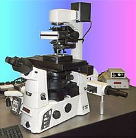
A fully functional computer controlled unit for the multiple spot trapping and manipulation of micron sized particles. It is designed to be attached to high quality commercial instruments, upgrading them to Photonic Force Microscopes, especially useful in mechanobiology experiments and biomechanics.
CATEGORY
This system is designed for single spot trapping and manipulation of micron sized particles. It is designed to be attached to a high-quality commercial instrument, converting it into a Photonic Force Microscope (PFM), especially in mechanobiology experiments and biomechanics.
CATEGORY
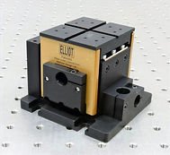
2 mm coarse travel per axis 4.5 kg load capacity Minimal arcuate displacement Orthogonal alignment grooves Use any combination of Elliot Scientific adjuster types Ultra-stable patented† design XYZ flexure stage
CATEGORY
