By ASML
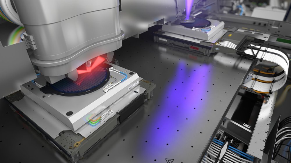
The PAS 5500/8TFH-A KrF Step-and-Scan system is a dedicated lithography tool for thin-film head (TFH) production on 125-mm, 150-mm, and 200-mm AlTiC wafers. It combines a powerful, variable NA up to 0.8 lens with the proven thick AlTiC wafer handling of a PAS body and specific alignment improvements for the TFH environment. The result is a new standard for TFH production at current and future technology nodes. TFH manufacturing involves printing sub-100-nm isolated features, which demands extremely low lens aberration levels. The PAS 5500/8TFH-A uses the proven ultra-low aberration KrF lens from the XT platform on the PAS body, ensuring excellent performance and a low cost of ownership. The low thermal conductivity of AlTiC wafers means maximum throughput on the track is restricted, allowing the PAS 5500/8TFH-A more time for alignment and wafer stabilization. In addition, the PAS 5500/8TFH-A features further improvements to the dynamics. Together, these translate into industry-leading overlay and stitching performance on AlTiC wafers. Technical Specifications Lens Wavelength: 248 nm NA: 0.55-0.80 (variable) Resolution: ≤ 110 nm Field size, for reticle with pellicle • Max X: 26.0 mm • Max Y: 33.0 mm CD Uniformity @ 90-nm isolated lines • BF: ≤ 6 nm • Over 0.3-μm defocus: ≤ 14 nm CD Uniformity @ 110-nm L/S • BF: ≤ 7 nm • Over 0.4-μm defocus: ≤ 10 nm Distortion (Dynamic): ≤ 9 nm Image plane deviation: ≤ 55 nm Astigmatism: ≤ 40 nm Overlay Single-machine on AlTiC: ≤ 8 nm Matched-machine on AlTiC: ≤ 17 nm TFH Specific Stage grid verification XY, YX on AlTiC: < 8 nm Colinearity using 3 fields for 2" rowbars on AlTiC: < 15 nm Wafer Throughput 50-mJ/cm 2 exposure dose, for critical overlay layers • 200-mm wafers, 46 shots: ≥ 25 wph Illumination and Dose Control Integrated slit uniformity: ≤ 0.5% Lasers Type: Cymer ELS6610 Power: 20 W Beam Delivery: ≤ 20-m remote capability Key Features and Benefits SmartStart Enables user-defined wafer accommodation, meandering routing in X, and system start-up via the job definition to provide stable production performance for small AlTiC wafer batch sizes in combination with TFH-specific off-line data analysis software. Proven AlTiC Wafer Handling Proven handling of 1.2 mm thick (125 mm, 150 mm or 200 mm diameter) and 2.0 mm thick (125 mm and 150 mm diameter) AlTiC wafers. KrF Starlith 870 Projection Lens with Variable NA Up to 0.80 Ultra-low aberration levels enable isolated line imaging below 90 nm. UNICOM, ADE UNICOM enables automatic optimization of the slit uniformity per illumination setting. Meanwhile, the automatic DOE exchanger (ADE) can hold up to 5 Diffractive Optical Elements (DOEs). IOSc-4 The latest overlay capability configuration. PAS 5500 Step-and-Scan Body Improved dynamics and interferometer control enable best-in-class performance. Multiple Exposure Technique Enables different illumination modes and imaging settings with multiple masks, and allows user-defined image sequence orders.
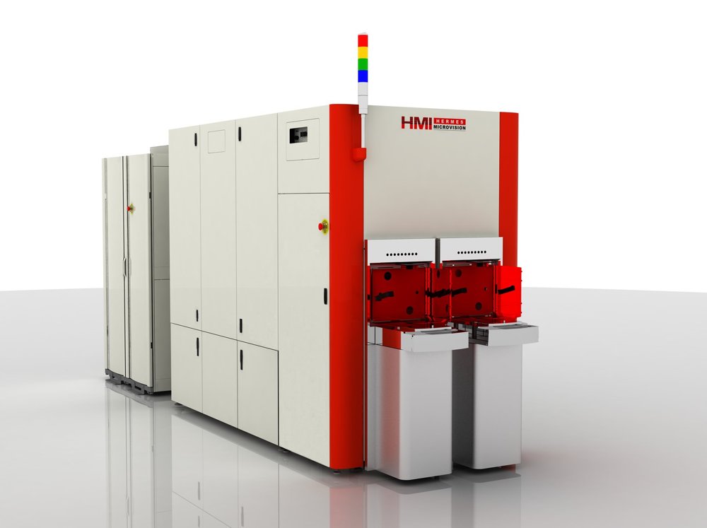
For today’s advanced microchips, defects as small as a couple of nanometers can render the entire chip useless. With its 1-nanometer resolution, e-beam inspection offers just the right kind of eyes to spot those tiny misprints. ASML is at the forefront of developments in e-beam metrology and inspection. E-beam achieves a higher resolution than YieldStar, but it measures more slowly, which means that it’s typically used after the pattern is etched onto the wafer. ‘E’ is for ‘electron’ E-beam technology has been around for decades. The basic concept is that a metal wire is heated until it gives off electrons, which are accelerated and formed into a beam by electric and magnetic fields. Unlike visible and ultraviolet light (but just like extreme ultraviolet light) electron beams must travel in a vacuum so they are not deflected or absorbed before reaching the target. In metrology and inspection in the semiconductor industry, the e-beam scans across the wafer. The electrons strike the surface and penetrate a small distance into the material, generating new 'secondary electrons' before being scattered. Just as with diffraction-based measurements, measuring the scattering of secondary electrons allows us to build up a very high-resolution picture of the surface. The more focused the beam, the smaller the details that can be measured. Speeding up e-beam imaging The tricky thing with e-beam measurements is that they’re quite slow. As a result, they have only typically been used in the early R&D phase of chip manufacturing, where time is less of an issue. ASML is leading the way in speeding up e-beam measurements so that manufacturers can enjoy their benefits in volume production. One way we do that is by developing solutions that focus e-beam measurements on specific hotspots where defects are more likely or more critical. In-line wafer and reticle inspection By speeding up the process and narrowing down the search to specific areas, e-beam can be used directly in the production line for wafer inspection while maintaining productivity levels.
CATEGORY
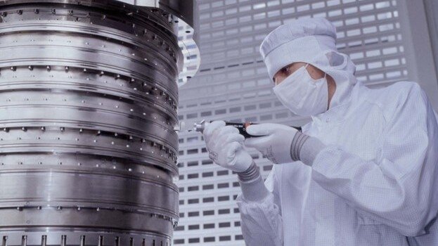
By autumn 2003, the immersion team was able to demonstrate concrete imaging results on the ASML prototype system dubbed the TWINSCAN AT:1150i. "The proto results changed the lithography roadmap almost instantly," Jan says. "We defined a series of new lithography systems in a very short period of time that would directly address the chip industry's resolution struggle."
CATEGORY
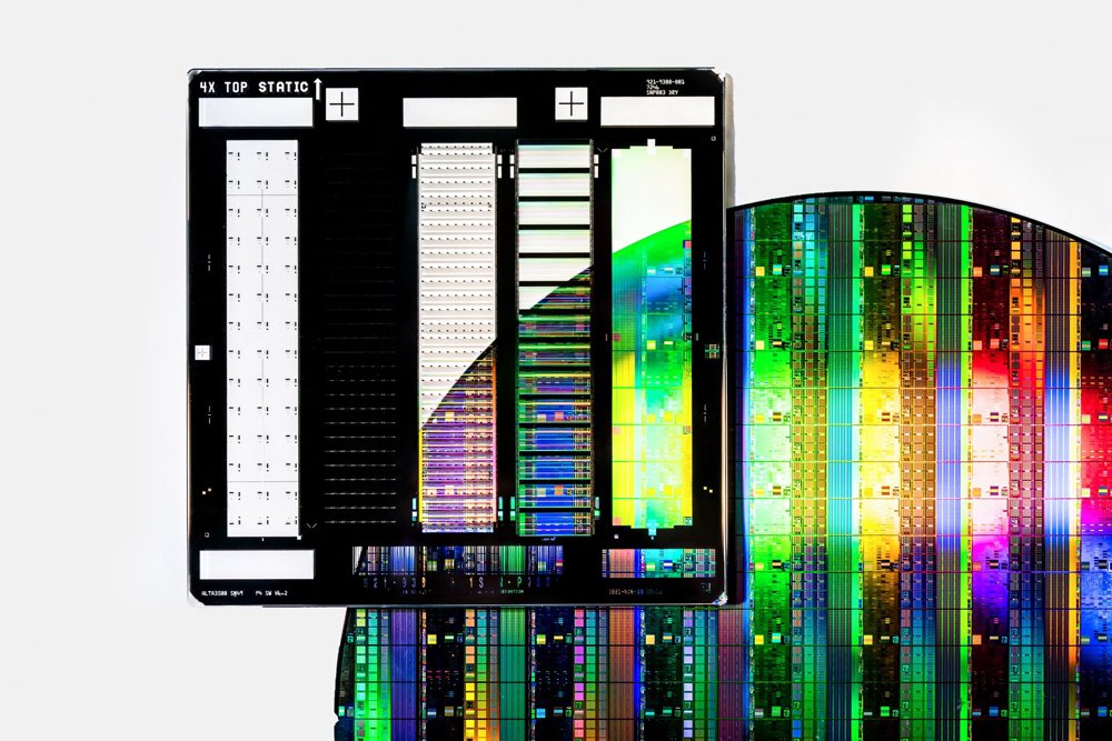
Using the vast amounts of data generated by our systems, computational lithography simulates the manufacturing process with powerful algorithms. These simulations help to design a chip blueprint (the reticle) that contains the pattern to be printed on the wafer. That's how we make sure that our lithography machines print what they should. This technique is called optical proximity correction (OPC) and is often combined with specific illumination optimizations in the lithography system. ASML's industry-leading computational lithography products enable accurate lithography simulations that help to improve chip yield and quality.
CATEGORY