By ASML
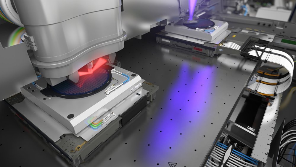
High Productivity i-Line Stepper The PAS 5500/275D is an i-line stepper stretching resolution down to 0.28 μm and beyond. It is built on the success of the proven PAS 5500/250C advanced i-line stepper. The PAS 5500/275D features improved imaging achieved by applying the latest techniques in lens adjustment as well as improved overlay by including phase modulation in the system. In addition to that, Image Quality Control is included as standard. Leadership productivity is improved to more than 100 wph (ATP settings). The PAS 5500/275D uses an AERIAL illuminator, which provides flexible and automated NA/sigma combinations in both conventional and off-axis illumination modes while maintaining high intensities to enable economical mass production of leading-edge devices. Technical Specifications Lens Wavelength: 365 nm NA: 0.48–0.60 (variable) Resolution: ≤ 0.28 μm Field size, for reticle with pellicle • Diameter: 31.1 mm • Max X: 22.0 mm • Max Y: 27.4 mm UDOF @ 0.28-μm with 10% CD Control (top-down) • Annular: ≥ 0.8 μm Distortion: ≤ 40 nm Overlay 99.7% with 2 pt. global alignment • Single-machine: ≤ 40 nm • Matched to PAS 5500/275: ≤ 80 nm Production throughput 200-mJ/cm 2 exposure dose • 150-mm wafers, 40 shots: ≥ 120 wph • 200-mm wafers, 70 shots: ≥ 100 wph AERIAL Illumination Conventional • Intensity: ≥ 2250 mW/cm 2 (@ NA 0.56) • max: ≤ 0.8 • min: ≥ 0.35 • Uniformity: ≤ 1.4% Annular • Intensity: ≤ 1900 mW/cm 2 (@ NA 0.60) • out: ≤ 0.85 • in: ≤ 0.20 • out-in: ≥ 0.25 • Uniformity: ≤ 1.2% Batch Streaming with ARMS Continuous-flow manufacturing. Key Features and Benefits Variable, High-NA i-line Lens Production resolution down to 0.28 μm. Innovative 3.5-kW AERIAL Illuminator Maximum throughput over partial coherence and annular range. Continuously variable partial coherence and annular illumination using AERIAL Optics Process latitude optimization for different process layers. Software-controlled Lens NA and Illuminator Flexible automated imaging optimization in production settings. Focused Reticle Masking System Maximizes available reticle area. Direct Reticle-referenced, Through-The-Lens (TTL) Phase-grating Alignment Optimum overlay and matching using alignment beam phase modulation. Advanced High Speed Stage Precision with high throughput.
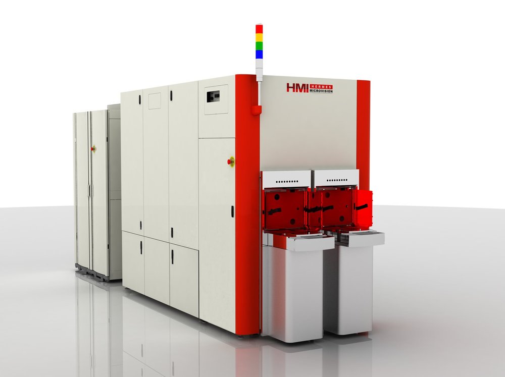
For today’s advanced microchips, defects as small as a couple of nanometers can render the entire chip useless. With its 1-nanometer resolution, e-beam inspection offers just the right kind of eyes to spot those tiny misprints. ASML is at the forefront of developments in e-beam metrology and inspection. E-beam achieves a higher resolution than YieldStar, but it measures more slowly, which means that it’s typically used after the pattern is etched onto the wafer. ‘E’ is for ‘electron’ E-beam technology has been around for decades. The basic concept is that a metal wire is heated until it gives off electrons, which are accelerated and formed into a beam by electric and magnetic fields. Unlike visible and ultraviolet light (but just like extreme ultraviolet light) electron beams must travel in a vacuum so they are not deflected or absorbed before reaching the target. In metrology and inspection in the semiconductor industry, the e-beam scans across the wafer. The electrons strike the surface and penetrate a small distance into the material, generating new 'secondary electrons' before being scattered. Just as with diffraction-based measurements, measuring the scattering of secondary electrons allows us to build up a very high-resolution picture of the surface. The more focused the beam, the smaller the details that can be measured. Speeding up e-beam imaging The tricky thing with e-beam measurements is that they’re quite slow. As a result, they have only typically been used in the early R&D phase of chip manufacturing, where time is less of an issue. ASML is leading the way in speeding up e-beam measurements so that manufacturers can enjoy their benefits in volume production. One way we do that is by developing solutions that focus e-beam measurements on specific hotspots where defects are more likely or more critical. In-line wafer and reticle inspection By speeding up the process and narrowing down the search to specific areas, e-beam can be used directly in the production line for wafer inspection while maintaining productivity levels.
CATEGORY
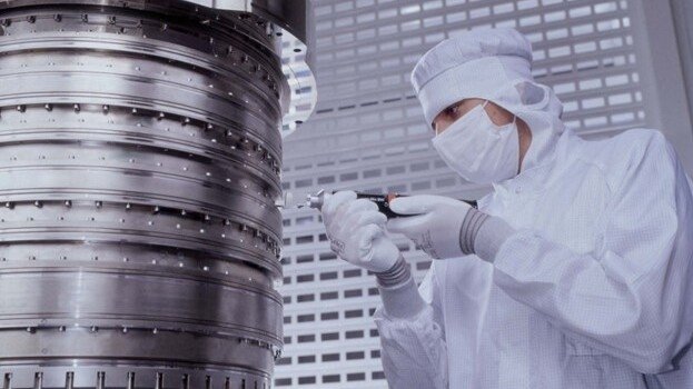
By autumn 2003, the immersion team was able to demonstrate concrete imaging results on the ASML prototype system dubbed the TWINSCAN AT:1150i. "The proto results changed the lithography roadmap almost instantly," Jan says. "We defined a series of new lithography systems in a very short period of time that would directly address the chip industry's resolution struggle."
CATEGORY
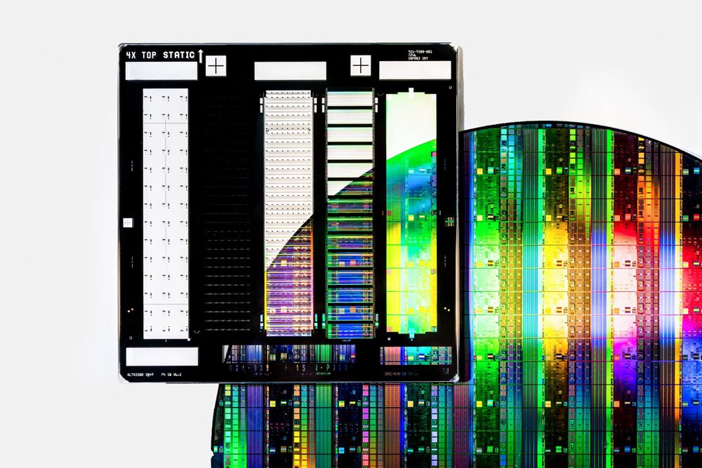
Using the vast amounts of data generated by our systems, computational lithography simulates the manufacturing process with powerful algorithms. These simulations help to design a chip blueprint (the reticle) that contains the pattern to be printed on the wafer. That's how we make sure that our lithography machines print what they should. This technique is called optical proximity correction (OPC) and is often combined with specific illumination optimizations in the lithography system. ASML's industry-leading computational lithography products enable accurate lithography simulations that help to improve chip yield and quality.
CATEGORY