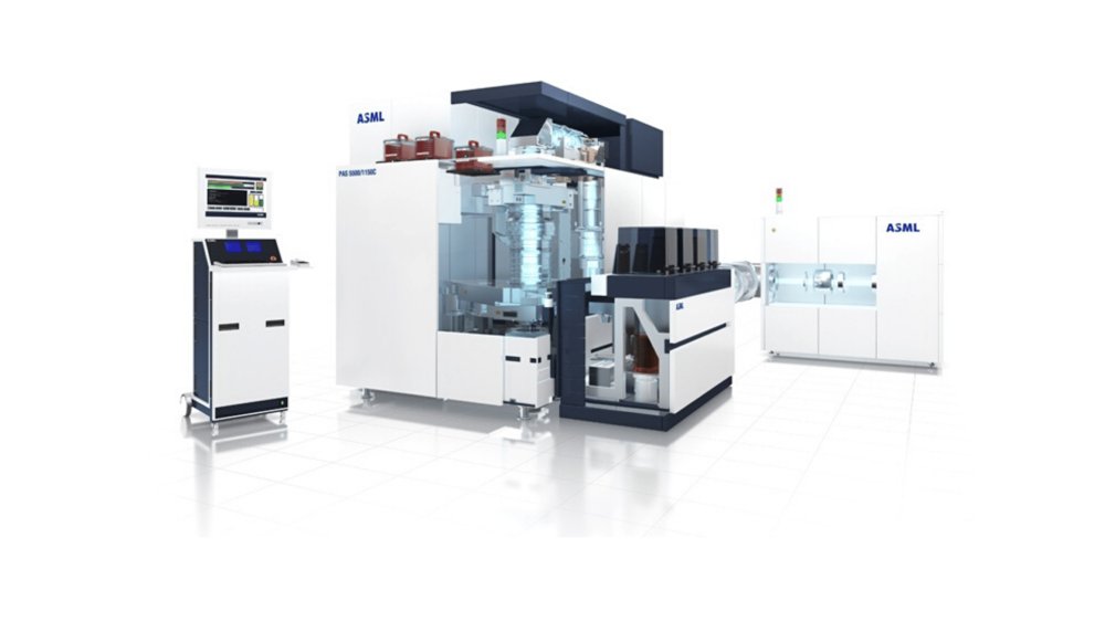
By ASML
Refurbished PAS 5500 systems are built on a versatile, multifunctional platform, which makes them adaptable for a wide range of emerging markets and specialized applications. The platform supports front-to-backside alignment – an essential capability for aligning layers on opposite sides of a wafer in advanced 3D structures such as MEMS chips. It also offers the flexibility to process a wide variety of materials and enables the integration of multi-layer compound devices, which are critical for modern power electronics. PAS systems can also be optimized for small wafer sizes (3-inch, 4-inch, and 6-inch), which are commonly used in applications such as silicon photonics – including distributed feedback (DFB) lasers for AI data centers. Other applications include radio-frequency devices with non-silicon substrates and thin-film heads for hard disk drives. Both throughput and overlay performance can be tuned to meet specific production requirements, enabling cost optimization in high-volume manufacturing environments.
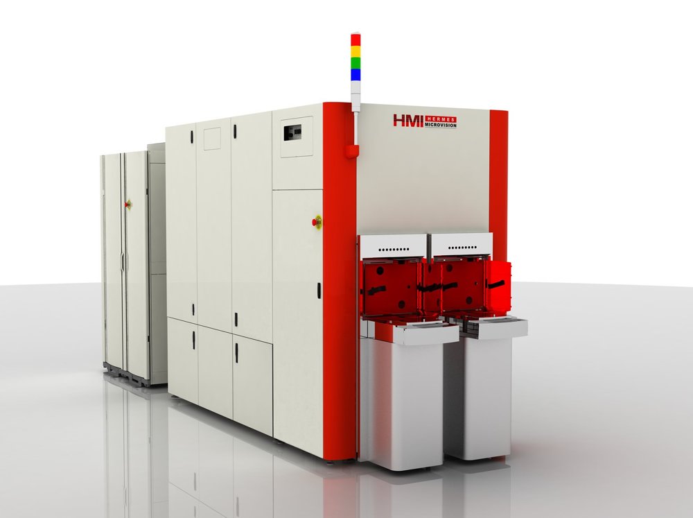
For today’s advanced microchips, defects as small as a couple of nanometers can render the entire chip useless. With its 1-nanometer resolution, e-beam inspection offers just the right kind of eyes to spot those tiny misprints. ASML is at the forefront of developments in e-beam metrology and inspection. E-beam achieves a higher resolution than YieldStar, but it measures more slowly, which means that it’s typically used after the pattern is etched onto the wafer. ‘E’ is for ‘electron’ E-beam technology has been around for decades. The basic concept is that a metal wire is heated until it gives off electrons, which are accelerated and formed into a beam by electric and magnetic fields. Unlike visible and ultraviolet light (but just like extreme ultraviolet light) electron beams must travel in a vacuum so they are not deflected or absorbed before reaching the target. In metrology and inspection in the semiconductor industry, the e-beam scans across the wafer. The electrons strike the surface and penetrate a small distance into the material, generating new 'secondary electrons' before being scattered. Just as with diffraction-based measurements, measuring the scattering of secondary electrons allows us to build up a very high-resolution picture of the surface. The more focused the beam, the smaller the details that can be measured. Speeding up e-beam imaging The tricky thing with e-beam measurements is that they’re quite slow. As a result, they have only typically been used in the early R&D phase of chip manufacturing, where time is less of an issue. ASML is leading the way in speeding up e-beam measurements so that manufacturers can enjoy their benefits in volume production. One way we do that is by developing solutions that focus e-beam measurements on specific hotspots where defects are more likely or more critical. In-line wafer and reticle inspection By speeding up the process and narrowing down the search to specific areas, e-beam can be used directly in the production line for wafer inspection while maintaining productivity levels.
CATEGORY
Our highest-resolution e-beam system to date, the eP5 offers critical dimension (CD) metrology and defect detection at high throughput. The eP5 is as at home in the fab as it is in the R&D lab, allowing chipmakers to monitor process performance in production and verify optical proximity correction (OPC) models in development. 01. Versatility The eP5 combines precise CD metrology with high-resolution defect detection in one system. For wafer inspection, it can operate in both physical defect and voltage contrast mode to detect patterning and electrical defects. 02. Sensitivity With a 1 nm pixel size, the eP5 is our highest-resolution e-beam system. It is capable of detecting defects down to 5 nm and achieves < 0.1 nm CD precision with 0.05 nm measurement sensitivity. It offers industry-leading auto defect classification (ADC), while our die-to-database (D2DB) feature uses design information to further improve defect sensitivity and classification. 03. Throughput A large (12,000 x 12,000 pixel) field of view enables high scanning throughput. Additionally, the eP5 can carry out CD metrology and wafer inspection at the same time to maximize productivity.
CATEGORY
The pattern fidelity metrology option available on the eP5 allows chipmakers to harness the superfine resolution of e-beam solutions at even greater throughputs to monitor high-volume production processes. The option draws data from a wide variety of sources including our TWINSCAN lithography systems, our optical YieldStar and computational metrology systems, and the eP5 itself as well as our computational lithography solutions and non-ASML equipment. It then analyzes this data to identify hotspots where defects are most probable, using this insight to guide and optimize scan strategies in the eP5. This allows chipmakers to maximize inspection throughput while still detecting yield-limiting defects.
CATEGORY
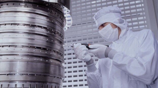
By autumn 2003, the immersion team was able to demonstrate concrete imaging results on the ASML prototype system dubbed the TWINSCAN AT:1150i. "The proto results changed the lithography roadmap almost instantly," Jan says. "We defined a series of new lithography systems in a very short period of time that would directly address the chip industry's resolution struggle."
CATEGORY
