ANT Ray Tracer v3.1 Save.antTRACE Load.antTRACE Global Settings Display Units (Z-Axis) Display Units (Y-Axis) Photons per Ray Force Start Z Force End Z Sources Mode: Div: Dia/Len: Brightness [photons · s⁻¹ · mm⁻² · mrad⁻² · (0.1% bandwidth)⁻¹]: Pos Z: Pos Y: Pt Srcs (Fill): 400 eV (≈ 3.10 nm) Optics Position Z Offset X & Y Diameter Diffraction Orders Order: Eff(%): Design f (m=1): 2.016 mm NA: 6.20e-2 Div (2θ): 124.06 mrad DOF: 0.40 µm Outer Opaque Ring Aperture Dia: Outer Dia: Central Opaque Stop Hole Transmittance (%) Outer Opaque Ring Aperture Dia: Central Opaque Stop Stop Dia: Hole Transmittance (%) T% (Black): T% (White): Phase(×π): Pixel Size: Mode: Pass light outside bounds Load Image Mask 288×288 px | 288.0×288.0 µm Design f (m=1): 1.936 mm NA: 5.17e-2 Div (2θ): 103.37 mrad DOF: 0.58 µm Detectors Detector 1 Position Z Offset X & Y Size (Width & Height) Resolution Mode Total Pixels (X and Y) Calculated Size: 78.125 µm/px View Detector Maps Auto Fit (Stretch)Auto Fit (1:1)Tool:Zoom Pan Ruler Clear Rulers Style:Integration Time:5s (501 rays / 5.01e+9 photons simulated)Z: 0, Y: 0 Ray limit exceeded! Trace cancelled to protect memory. Working... Cancel Trace Ray Orders On% Vis Col Ord Opacity: Detector Analysis Select Detector: Increase time: Integrate time Reset Cancel 2D spatial mapping (X vs Y) Auto-Max Max: View Mode: Log Scale Color by Order Reset View 1 mm 1D Histogram Shows integrated flux along Y-axis for entire detector.
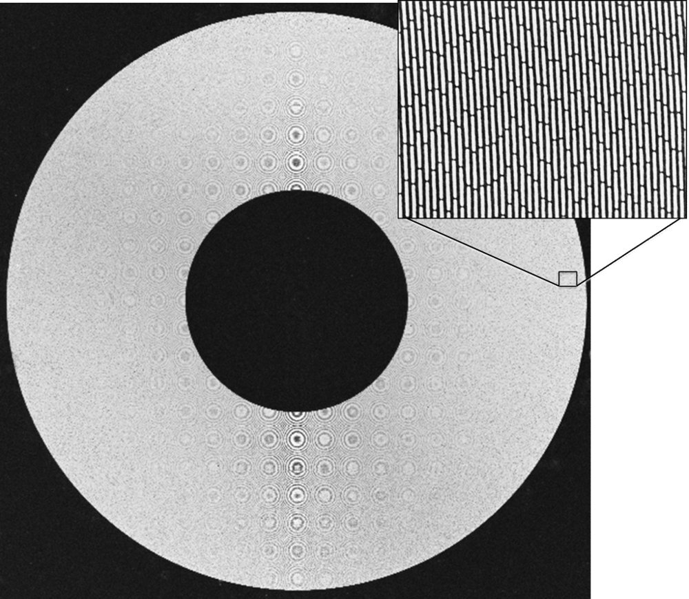
X-rays below 5 keV (<~0.25 nm) are typically classified as soft X-rays, where they are more readily absorbed than higher energy X-rays. Typically, zone plates do not require the same thickness for efficiency and allow for higher resolution imaging. A range of zone plate options for soft/tender X-Rays are available for specific requirements. (Custom Designs Available) Device | Outer Zone Width ΔR n (nm) | Thickness (µm) | Outer Diameter (µm) | ( of zones) E/ΔE Limit | ~ Focal Length(µm) SZP‑90um‑15nm | 15 | <0.07 | 90 | 1514 | 325 SZP‑120um‑15nm | 120 | 2019 | 433 SZP‑200um‑18nm | 18 | <0.15 | 200 | 2797 | 868 SZP‑270um‑18nm | 270 | 3775 | 1172 SZP‑320um‑18nm | 320 | 4473 | 1389 SZP-200um-25nm | 25 | <0.24 | 200 | 2007 | 1207 SZP‑250um‑25nm | 250 | 2509 | 1510 SZP-300um-25nm | 300 | 3010 | 1811 SZP-360um-25nm | 360 | 3612 | 2173 TZP‑160um‑50nm | 50 | <0.75 | 160 | 801 | 1934 TZP‑280um‑50nm | 280 | 1401 | 3384 TZP‑750um‑200nm | 200 | <0.75 | 750 | 938 | 36292 TZP‑1250um‑200nm | 1250 | 1563 | 60487 For estimated efficiency of zone plate, please see our online calculator at www.appliednt.com/zpcalc
CATEGORY
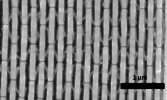
Zone plate efficiency for binary zone plates requires high aspect ratio structures which can survive high flux imaging systems. The “Oxide Interlock” option creates small interconnecting channels between metal zone of silicon dioxide which is transparent to hard X-rays and does not swell or distort, even when not under vacuum. These have been shown to significantly increase the zone plate efficiency and lifetime.
CATEGORY
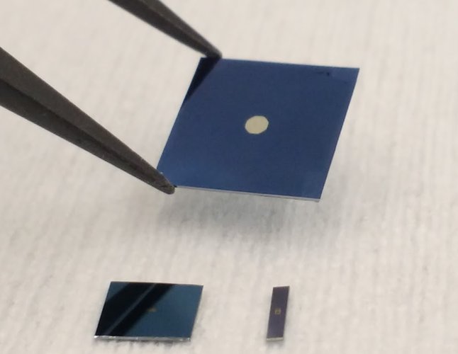
Our standard frame size is 5 mm x 5 mm. We also offer custom frame sizes. Membrane thickness can be down to 50 nm and silicon carbide membranes are available for those requiring long-lifetime membranes. Low stress 50 nm silicon nitride membrane Low stress 200 nm silicon carbide membrane Fused Silica Substrate (~500 um thick) Custom chip sizes
CATEGORY